
Light emitting unit operative at high coupling efficiency, optical sensor system and musical instrument using the same

Active Publication Date: 2006-10-17
YAMAHA CORP
View PDF4 Cites 4 Cited by
  • Summary
  • Abstract
  • Description
  • Claims
  • Application Information

AI Technical Summary

Benefits of technology

[0010]It is therefore an important object of the present invention to provide a light emitting unit, which achieves large coupling efficiency between a light emitting device and an optical fiber or fibers.
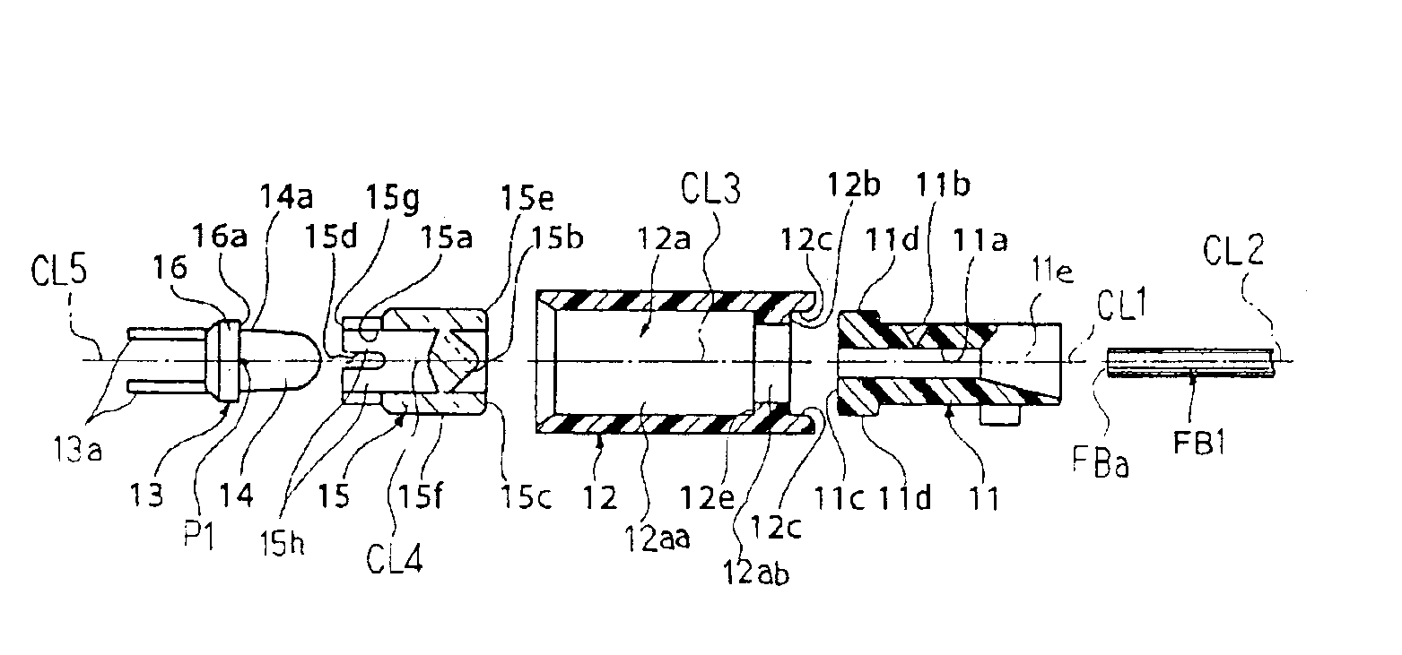
[0013]In accordance with one aspect of the present invention, there is provided a light emitting unit comprising a light emitting device for converting electric power to light, at least one optical fiber having a light input end on which the light is incident, a condenser lens having an optical axis and provided between the light emitting device and the light input end for condensing the light onto the light input end, a casing formed with a hollow space for keeping the light emitting device, the condenser lens and the light input end at intervals, and a light increaser formed in at least one of the casing, the condenser lens and the inner surface of the casing defining the hollow space for increasing the amount of light incident onto the light input end.
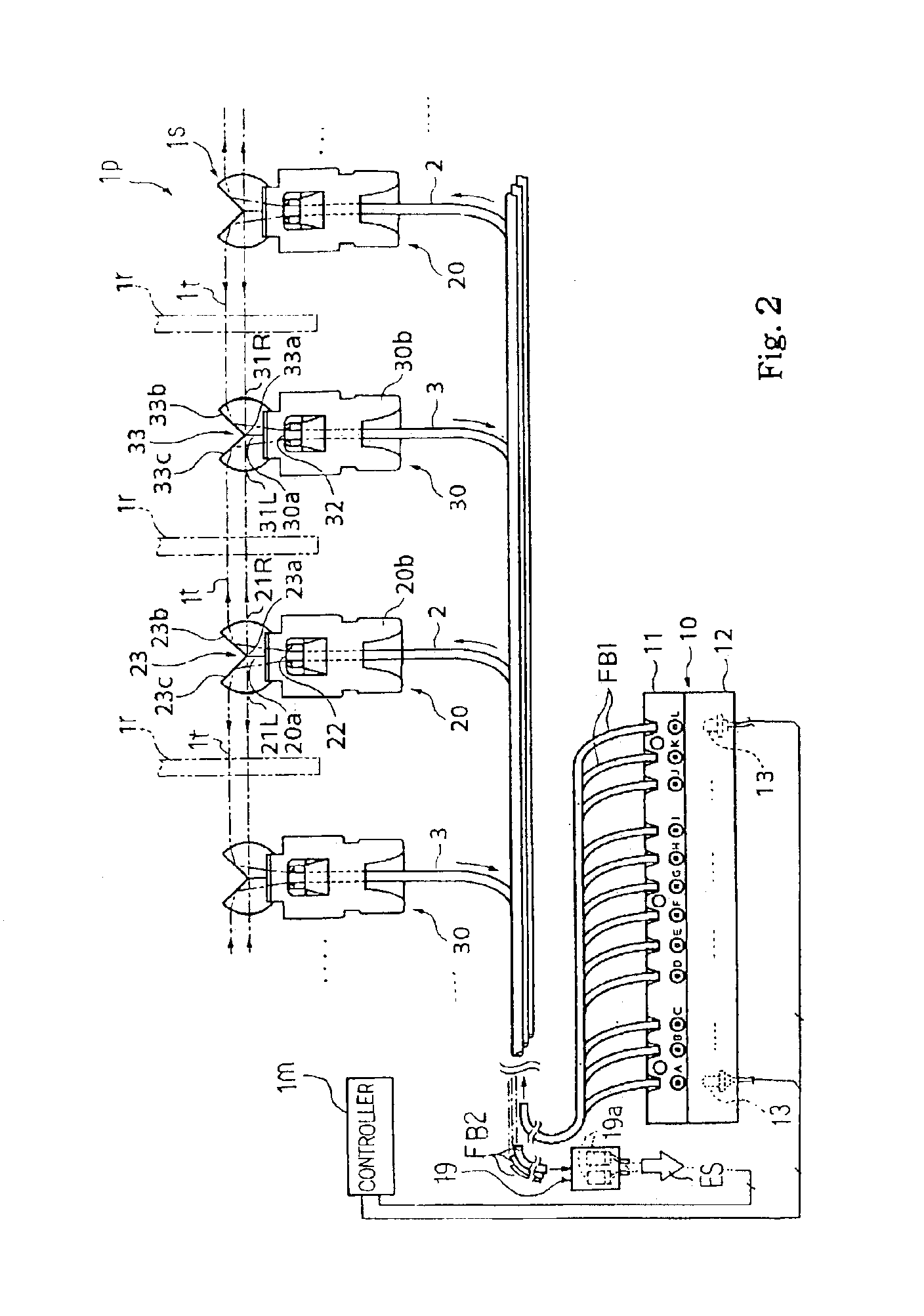
[0014]In accordance with another aspect of the present invention, there is provided an optical sensor system comprising at least one outward optical fiber having a first light input end and a first light output end and offering an outward path to a light, at least one light radiating optical sensor head connected to the first light output end and radiating the light in a certain direction, at least one light receiving optical sensor head opposed to the at least one light radiating optical sensor head and receiving the light radiated from the at least one light radiating optical sensor head, at least one homeward optical fiber having a second light input end connected to the at least one light receiving optical sensor head and a second light output end and offering a homeward path to the light, at least one obstacle secured to a moving object and having a trajectory across the light radiated from the at least one light radiating optical sensor head to the at least one light receiving optical sensor head for intersecting the light during a travel along the trajectory, a light detecting unit connected to the second light output end for converting the light to an electric signal and a light emitting unit connected to the first light input end, and the light emitting unit includes a light emitting device for converting electric power to the light, a condenser lens having an optical axis and provided between the light emitting device and the first light input end for condensing the light onto the first light input end, a casing formed with a hollow space for keeping the light emitting device, the condenser lens and the first light input end at intervals and a light increaser formed in at least one of the casing, the condenser lens and the inner surface of the casing defining the hollow space for increasing the amount of the light incident onto the first light input end.
[0015]In accordance with yet another aspect of the present invention, there is provided a musical instrument for electronically generating sound comprising a sound generating system for electronically generating the sound, at least one movable object moved by a player for requesting the sound generating system to electronically generate the sound and an optical sensor system monitoring the at least one movable object and connected to the sound generating system for notifying the sound generating system of the player's request, and the optical sensor system includes at least one outward optical fiber having a first light input end and a first light output end and offering an outward path to a light, at least one light radiating optical sensor head connected to the first light output end and radiating the light across a trajectory of the at least one movable object, at least one light receiving optical sensor head opposed to the at least one light radiating optical sensor head and receiving the light radiated from the at least one light radiating optical sensor head across the trajectory, at least one homeward optical fiber having a second light input end connected to the at least one light receiving optical sensor head and a second light output end and offering a homeward path to the light, at least one obstacle secured to the at least one moving object, intersecting the light during a travel of the at least one moving object along the trajectory, a light detecting unit connected to the second light output end for converting the light to an electric signal representative of the player's request and a light emitting unit connected to the first light input end and having a light emitting device for converting electric power to the light, a condenser lens having an optical axis and provided between the light emitting device and the first light input end for condensing the light onto the first light input end, a casing formed with a hollow space for keeping the light emitting device, the condenser lens and the first light input end at intervals and a light increaser formed in at least one of the casing, the condenser lens and the inner surface of the casing defining the hollow space for increasing the amount of the light incident onto the first light input end.

Problems solved by technology

This is uneconomical.
A problem is encountered in the prior art light emitting unit in low coupling efficiency.
However, the optical fiber connector can not guarantee that the light input end of the optical fiber should be disposed at the target position on the optical axis of the condenser lens.
Thus, the deviation from the target position is causative of the low coupling efficiency.
Another reason for the low coupling efficiency is the aberration.
Thus, the aberration is also causative of the low coupling efficiency.
Yet another reason for the low coupling efficiency is the attenuation and absorption on the inner surface of the optical fiber connector.

Method used


Image

  • Light emitting unit operative at high coupling efficiency, optical sensor system and musical instrument using the same
  • Light emitting unit operative at high coupling efficiency, optical sensor system and musical instrument using the same
  • Light emitting unit operative at high coupling efficiency, optical sensor system and musical instrument using the same

Examples


first embodiment

Keyboard Musical Instrument

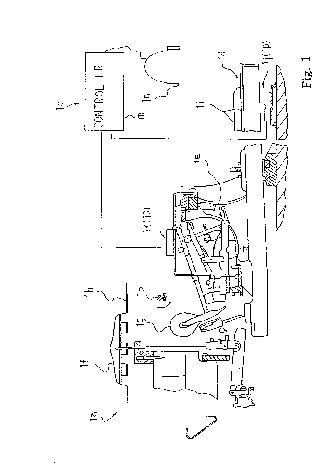
[0024]Referring to FIG. 1 of the drawings, a composite keyboard musical instrument largely comprises an acoustic piano 1a, a hammer stopper 1b and an electronic tone generating system 1c. While a user is keeping the hammer stopper 1b at a free position, acoustic piano tones are selectively generated from the acoustic piano 1a through fingering. When the user changes the hammer stopper 1b to a blocking position, the hammer stopper 1b prohibits the acoustic piano 1a from generating the acoustic piano tones. The electronic tone generating system 1c responds to user's fingering, and generates electronic tones instead of the acoustic piano tones.

[0025]The acoustic piano 1a includes a keyboard 1d, action units 1c, dampers 1f, hammers 1g and strings 1h. Eighty-eight black / white keys 1i are incorporated in the keyboard 1d. The user selectively depresses and releases the black / white keys 1i. The depressed keys 1i make the dampers 1f spaced from the strings 1h, and ...

second embodiment

[0060]Turning to FIG. 5 of the drawings, another light emitting unit 10A embodying the present invention includes light emitting diodes 13 and condenser lens units 15A. The light emitting unit 10A forms a part of the optical sensor system, which is incorporated in the keyboard musical instrument. In other words, the condenser lens units 15 are replaced with the condenser lens units 15A. Although the bundle FB1 and the condenser lens units / light emitting diodes 15A / 13 are maintained in an optical fiber plug and a light emitting device holder, the optical fiber plug and light emitting device holder are not shown in FIG. 5, because the optical fiber plug 11 and light emitting device holder 12 are available for the light emitting unit 10A. In this instance, the condenser lens units 15A are advantageous over the condenser lens units 15. For this reason, description is hereinafter focused on the condenser lens units 15.

[0061]The condenser lens 15ba has a rear surface 15bb and a front surf...

third embodiment

[0062]FIG. 6 shows yet another light emitting unit 10B embodying the present invention. The light emitting unit 10B forms a part of the optical sensor system, which in turn forms a part of the composite keyboard musical instrument. The light emitting unit 10B includes an optical fiber plug 111, a light-emitting device holder 112, a light emitting device 113 and a condenser lens unit 115. The optical fiber plug 111, light emitting device holder 112 and condenser lens unit 115 are made of the material used for the optical fiber plug 11, light emitting device holder 12 and condenser lens unit 15.

[0063]The optical fiber plug 111 is formed with through-holes, and bundles FB1 of optical fibers 2 are secured to the optical fiber plug 111 in the through-holes. The transparent adhesive compound may be used for securing the bundles FB1 to the inner surfaces of the optical fiber plug 111. The bundles FB1 of optical fibers 2 have respective light input ends FBa substantially coplanar with the r...


PUM


Abstract

A light emitting device includes an optical fiber plug formed with a through-hole into which a bundle of optical fibers is inserted and a light-emitting device holder formed with a through-hole in which a condenser lens and a light emitting device are accommodated, and the optical fiber plug is assembled with the light-emitting device holder so that the light emitting device is optically coupled to the optical fiber through the condenser lens; a positioning device, a hyperboloid lens surface or a reflecting surface is formed in the optical fiber plug / light emitting device holder, condenser lens or the inner surface of the light-emitting device holder so that the light incident on the light input end is increased by virtue of the exact positioning between the optical fiber and optical axis, reduction of aberration or increase of light directed to the condenser lens.

Description

FIELD OF THE INVENTION[0001]This invention relates to a light emitting unit and, more particularly, to a light emitting unit for supplying light to an optical fiber, an optical sensor system using the same and a musical instrument equipped with the optical sensor system.DESCRIPTION OF THE RELATED ART[0002]Optical fibers have found wide varieties of application fields. The optical fibers are so flexible that user can easily route the optical fibers in a narrow crowded space. In fact, the optical fibers have been used as data transmission lines in a musical instrument such as, for example, a composite keyboard instrument. The composite keyboard instrument is designed on the basis of an acoustic piano. The component parts such as keys, key action units, hammers, dampers and strings are packed in a narrow space inside a cabinet. The keys are linked with the key action units and damper units, and the hammers are driven for rotation by depressed keys so as to strike the associated strings...

Claims


Application Information

Patent Timeline
IPC IPC(8): G02B6/00G02B6/36G02B6/32G02B6/42G02B6/43G10C3/12G10G3/00H01L33/58
CPCG02B6/4204G02B6/4292G02B6/4298G10C3/12G10G3/00G02B6/322G02B6/43
Inventor KATO, TADAHARUMURAMATSU, SHIGERUSASAKI, TSUTOMU
Owner YAMAHA CORP
Learn More