
Transparent optical element and method for adjusting light field to penetrate through transparent optical element

An optical element and adjustment method technology, applied in the field of micro-nano optics, can solve the problems of uneven distribution of scattering particles, high production cost, low transmittance, etc., achieve uniform anti-glare effect, reduce haze, and eliminate moiré interference fringes Effect

Active Publication Date: 2022-03-01
深圳市雕拓科技有限公司
View PDF11 Cites 2 Cited by
  • Summary
  • Abstract
  • Description
  • Claims
  • Application Information

AI Technical Summary

Problems solved by technology

[0005] The scattering of existing anti-glare micro-nano particles has the following disadvantages: First, the production is prone to uneven distribution of scattering particles. For high PPI, such as the display of mobile phone screens , it is easy to produce scattered points visible to the naked eye; second, the production cost is relatively high; third, due to the scattering effect of particles, the transmittance is low, etc.

Method used


Image

  • Transparent optical element and method for adjusting light field to penetrate through transparent optical element
  • Transparent optical element and method for adjusting light field to penetrate through transparent optical element
  • Transparent optical element and method for adjusting light field to penetrate through transparent optical element

Examples


Embodiment Construction

[0037] Embodiments of the present invention are described in detail below, examples of which are shown in the drawings, wherein the same or similar reference numerals designate the same or similar elements or elements having the same or similar functions throughout. The embodiments described below by referring to the figures are exemplary and are intended to explain the present invention and should not be construed as limiting the present invention.

[0038] In describing the present invention, it should be understood that the terms "length", "width", "upper", "lower", "front", "rear", "left", "right", "vertical", The orientation or positional relationship indicated by "horizontal", "top", "bottom", "inner", "outer", etc. are based on the orientation or positional relationship shown in the drawings, and are only for the convenience of describing the present invention and simplifying the description, rather than Nothing indicating or implying that a referenced device or element...


PUM

PropertyMeasurementUnit
heightaaaaaaaaaa
diameteraaaaaaaaaa

Abstract

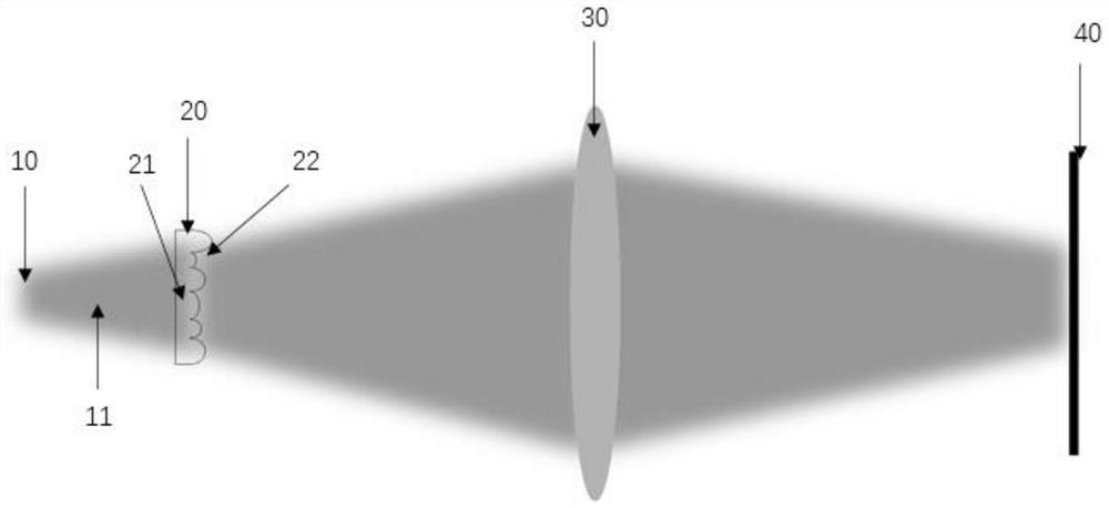
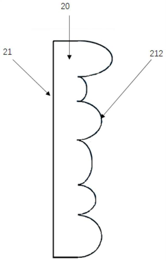
The invention provides a transparent optical element and a method for adjusting a light field penetrating through the transparent optical element. The adjusting method comprises the following steps: S1, carrying out light field tracing on incident light entering a micro-lens array of the transparent optical element; s2, performing light field tracing on the first incident light field through emergent light of a micro-lens array of the transparent optical element; s3, the second incident light field penetrates through the crystalline lens of the observer and forms emergent light, the emergent light is tracked, and the emergent light passes through the retina of the observer and forms a projection light field; s4, obtaining the intensity of a light field distributed on the retina of the observer; and S5, according to the light field intensity distributed on the retina of the observer, obtaining the mean square error of the pixel intensity distribution of the retina of the observer, and performing optimization by taking the minimum value of the mean square error as a target. According to the invention, the randomly distributed micro-lens array is utilized to realize glare elimination based on the reflection principle, and a light field passes through the surfaces of the micro-lenses, so that the mirror reflection energy is greatly reduced, and the anti-glare effect is achieved.

Description

technical field [0001] The invention relates to the field of micro-nano optics, in particular to a transparent optical element and a method for adjusting a light field passing through the transparent optical element. Background technique [0002] Anti-glare is to reduce the specular reflection of the sunlight or light incident on the surface of the object through scattering or reflection, so that the reflected light entering the observer's glasses becomes less, so that the observer's glasses are not irradiated by strong reflected light. , to protect the eye health of observers, especially when using electronic screens that are becoming more and more popular. [0003] A large number of existing anti-glare implementation technologies are based on the use of micro-nano structures to scatter incident light. When light waves irradiate nanostructured particles, according to the Mie scattering theory, light waves will be scattered in all directions, so that the energy of light wav...

Claims


Application Information

Patent Timeline
Patent Type & Authority Applications(China)
IPC IPC(8): G02B3/00G02B27/00
CPCG02B3/0006G02B3/0037G02B27/0012
Inventor 史瑞娄飞
Owner 深圳市雕拓科技有限公司
Learn More