
Large-stroke air flow air duct and snowmaker thereof

A technology with gas flow and large stroke, applied in the field of air ducts and snow making, it can solve the problems of short contact time of droplets, high manufacturing cost, insufficient heat exchange, etc., so as to improve the floating time of ice cores and increase the contact time. , Improve the effect of snow making

Active Publication Date: 2022-03-01
BEIJING UNIVERSITY OF CIVIL ENGINEERING AND ARCHITECTURE
View PDF9 Cites 0 Cited by
  • Summary
  • Abstract
  • Description
  • Claims
  • Application Information

AI Technical Summary

Problems solved by technology

[0004] Existing snowmaking machines mainly adopt the second method, that is, relying on the external cold environment to fully exchange heat between fog droplets and cold air to form ice crystals and ice nuclei, and then continue to form snowflakes; the current existing snowmaking machines, fan motors At the rear side of the blower, cold air is sucked from the external environment into the inside of the blower; the existing snow gun relies on the external cold environment, the contact time of the fog droplets is short, and the heat exchange is insufficient, resulting in insufficient snow production; in the prior art There is a snowmaking device with a gas vortex tube whose application number is 200420072748.4, which utilizes the hot and cold properties of the vortex tube to connect it to the air compressor through a compressed air pipeline. The snow machine depends on the environment, but its manufacturing cost is relatively high, and the device relies too much on the air compressor

Method used


Image

  • Large-stroke air flow air duct and snowmaker thereof
  • Large-stroke air flow air duct and snowmaker thereof
  • Large-stroke air flow air duct and snowmaker thereof

Examples


Embodiment Construction

[0023] The following will clearly and completely describe the technical solutions in the embodiments of the present invention with reference to the accompanying drawings in the embodiments of the present invention. Obviously, the described embodiments are only some, not all, embodiments of the present invention. Based on the embodiments of the present invention, all other embodiments obtained by persons of ordinary skill in the art without making creative efforts belong to the protection scope of the present invention.

[0024] The purpose of the present invention is to address the defects and deficiencies of the prior art, in order to increase the time for convective heat exchange between the atomized water droplets and the external cold air after being injected into the nozzle, and to reduce the dependence of the snow machine on snow conditions. On the basis of the swirling flow, the large-stroke gas flow fan and its snowmaking machine realize the technical purpose of more su...


PUM


Abstract

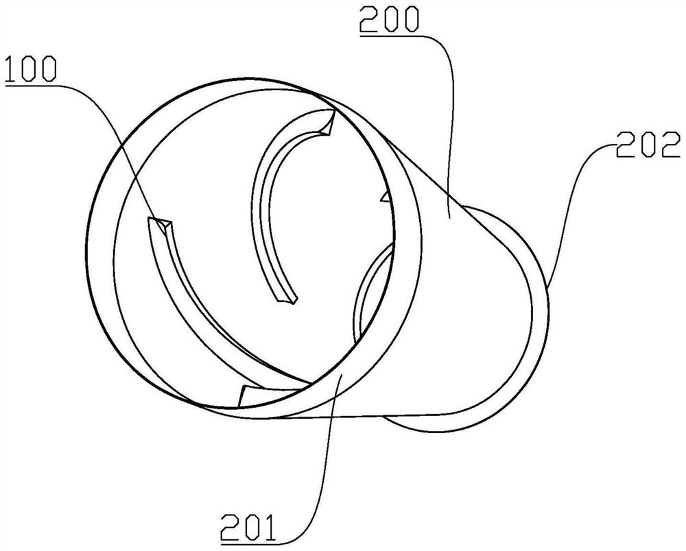
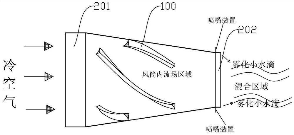
The invention discloses a large-stroke air flow air duct and a snowmaker thereof.The air duct comprises an air duct body and a plurality of flow guide plates evenly distributed on the inner wall of the air duct body at intervals in the circumferential direction, the flow guide plates extend in the length direction in a spiral progressive line mode in the axis direction of the air duct body, and the flow guide plates extend from the air duct fan motor end to the air duct nozzle end; the height extension directions of the flow guide plates all face the center of the air duct body, and a central axial air channel is defined by the flow guide plates; air flow axially flowing along the inner wall of the air duct body passes through the flow guide plate and then generates rotational flow, the phenomenon that cold air axially flowing along the inner wall of the air duct is directly and axially ejected and thrown in the environment without passing through the flow guide plate does not exist, the rotational flow changes the flow direction of the air in the duct body, so that the air forms longitudinal vortex along the inner wall of the air duct, and the air flow is more uniform. The flow stroke of cold air is increased, so that the contact time of atomized small water drops and the cold air is long, mixing is more violent, heat exchange is more sufficient, meanwhile, the floating time of ice cores is prolonged, the ice cores grow larger, and the snowmaking amount is increased.

Description

technical field [0001] The invention belongs to the technical field of blower and snowmaking, and in particular relates to a large-stroke gas flow blower and a snowmaking machine thereof. Background technique [0002] With the improvement of people's living standards, artificial snow is often required in scenes such as tourism and entertainment, film and television drama production, to form snowfall scenes or create snow-covered environments; [0003] There are two principles of snow making machine snow: the first is to use the ice making device to produce flake ice, and then use the flake ice as raw material to make snow. This method is cumbersome and complicated, and the snow quality is poor; High-pressure water and compressed air are mixed to make snow, and the high-pressure air generated by the compressor is sent to the nucleator, the central nucleator, and the water nozzle in front of the fan cylinder. Mixing, forming a mist, and then through the fan motor, the mist wa...

Claims


Application Information

Patent Timeline
IPC IPC(8): F25C3/04
CPCF25C3/04F25C2303/048
Inventor 徐荣吉宋文昊刘佳维王瑞祥吴海峰崔桢张鸿俊
Owner BEIJING UNIVERSITY OF CIVIL ENGINEERING AND ARCHITECTURE
Learn More