Single-pipe combination valve group wellhead flow path device easy to install

A combined valve and process technology, applied in wellbore/well valve devices, isolation devices, wellbore/well components, etc., can solve the problems of difficult installation, increased work steps, pipeline blockage, etc., and achieves fast and convenient installation. The effect of reducing work steps and improving thermal insulation performance

Inactive Publication Date: 2022-03-01
徐宏洋
View PDF0 Cites 0 Cited by
  • Summary
  • Abstract
  • Description
  • Claims
  • Application Information

AI Technical Summary

Problems solved by technology

[0003] The installation of the existing combined valve for single pipe is usually difficult, and it often takes a long time to disassemble and assemble. Therefore, when the combined valve is damaged as a whole and needs to be replaced, it often takes a long time. Correspondingly, it also increases the difficulty of workers' work, thereby reducing the practicability of the overall valve group. Secondly, the existing valve sealing is usually wrapped with cloth strips on the threaded openings to achieve the effect of filling the gaps between the threads. However, when the valve is replaced, the cloth strips often need to be rewound, which greatly increases the overall working steps, thus further reducing the practicability of the overall device and increasing the work intensity of the workers. Finally, the existing valves are connected The pipelines are usually installed outdoors, and the temperature is too low in winter, which may cause freezing of the internal fluid, resulting in the problem of pipeline blockage, so the overall process is not practical enough to adapt to temperature changes

Method used


Image

  • Single-pipe combination valve group wellhead flow path device easy to install
  • Single-pipe combination valve group wellhead flow path device easy to install
  • Single-pipe combination valve group wellhead flow path device easy to install

Examples


Embodiment Construction

[0027] The following will clearly and completely describe the technical solutions in the embodiments of the present invention with reference to the accompanying drawings in the embodiments of the present invention. Obviously, the described embodiments are only some, not all, embodiments of the present invention. Based on the embodiments of the present invention, all other embodiments obtained by persons of ordinary skill in the art without making creative efforts belong to the protection scope of the present invention.

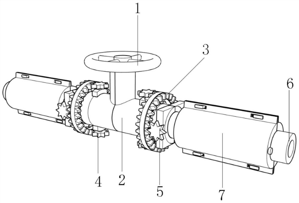
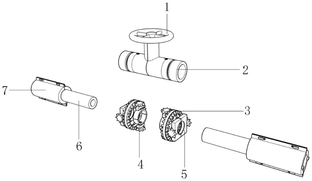
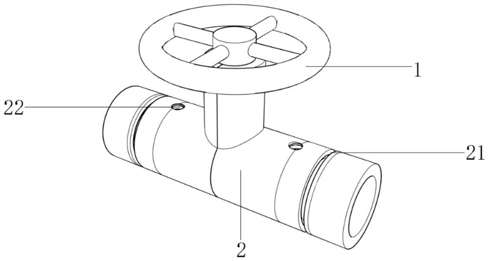
[0028] as attached Figure 1-7 An easy-to-install single-pipe combined valve group wellhead process device shown in the figure includes a knob 1, and a double-way connecting pipe 2 is installed on the bottom of the knob 1, and the left and right ends of the double-way connecting pipe 2 are movable. A rotating assembly 3 is installed, the left side of the rotating assembly 3 is movably installed with a disassembly assembly 4, the right side of the rotating asse...


PUM


Abstract

The invention discloses an easy-to-install single-pipe combination valve group wellhead flow device, and particularly relates to the technical field of oil well valves, the easy-to-install single-pipe combination valve group wellhead flow device comprises a knob, a two-way connecting pipe is movably installed at the bottom end of the knob, rotating assemblies are movably installed at the left end and the right end of the two-way connecting pipe, and dismounting assemblies are movably installed on the left sides of the rotating assemblies; a sealing assembly is movably installed on the right side of the rotating assembly, and conveying pipelines are detachably installed at the two ends of the two-way connecting pipe. By arranging the dismounting and mounting assembly, the pipeline and the valve can be mounted more quickly and conveniently, excessive time does not need to be spent, the structure is simple, operation of workers is facilitated, the working time of the workers is saved, meanwhile, the effect of improving the working efficiency of the workers is achieved, and therefore the effect of greatly improving the practicability of the whole device is achieved; and by arranging the sealing assembly, sealing work between the pipeline and the valve can be rapidly completed, the working steps of workers are reduced, and the effect of improving the practicability of the whole device is achieved.

Description

technical field [0001] The invention relates to the technical field of oil well valves, and more specifically, the invention relates to an easy-to-install wellhead flow device of a single-pipe combined valve group. Background technique [0002] Valves are pipeline accessories used to open and close pipelines, control flow direction, adjust and control the parameters (temperature, pressure and flow) of the conveying medium. According to their functions, they can be divided into shut-off valves, check valves, regulating valves, etc. Valves are the control components in the fluid delivery system. They have the functions of cut-off, adjustment, flow diversion, reverse flow prevention, pressure stabilization, flow diversion or overflow pressure relief. Valves used in fluid control systems range from the simplest cut-off valve to extremely complex The various valves used in the automatic control system have a wide variety of varieties and specifications. The valves can be used to ...

Claims


Application Information

Patent Timeline
Patent Type & Authority Applications(China)
IPC IPC(8): E21B34/02E21B36/00
CPCE21B34/02E21B36/00
Inventor 徐宏洋于立江管玉权
Owner 徐宏洋
Why Eureka
Try Eureka