High-speed electric arc machining device with inert gas protection function
A protection function, arc processing technology, applied in cleaning methods and utensils, metal material coating process, removal of smoke and dust, etc., can solve the problems of reduced protection effect, reduced service life of bellows, uneven thickness of protective layer, etc.
- Summary
- Abstract
- Description
- Claims
- Application Information
AI Technical Summary
Problems solved by technology
Method used
Image

Examples
Embodiment 1
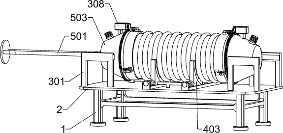
[0033] A high-speed arc machining device with inert gas protection function, such as Figure 1-11 As shown, it includes a support frame 1, a support plate 2, a clamping mechanism, a stabilizing mechanism, a spraying mechanism and a sealing mechanism. The upper side of 2 is provided with two sets of stabilizing mechanisms. The two sets of stabilizing mechanisms are respectively located on the left and right parts of the upper side of the support plate 2. The two sets of stabilizing mechanisms are located on the inner side of the clamping mechanism and are used for spraying the inner wall of the bellows. The spraying mechanism slides on the left part of the clamping mechanism, the sealing mechanism for discharging the air in the bellows is arranged on the right side of the spraying mechanism, and the spraying mechanism and the sealing mechanism are respectively matched with the inner wall of the bellows.
[0034] When using this device, the operator first connects the clamping m...
Embodiment 2
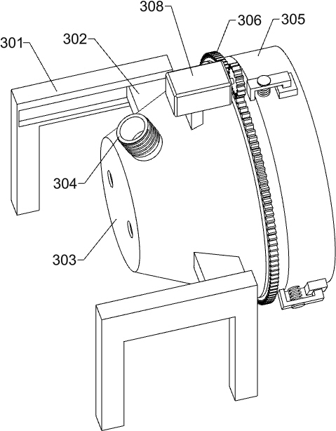
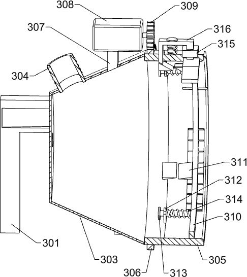
[0036] On the basis of Example 1, as Figure 2-4 As shown, the clamping mechanism includes an electric sliding rail 301, an electric sliding block 302, a conical shell 303, a one-way valve 304, a reel tube 305, a gear ring 306, a first fixing block 307, a first servo motor 308, a first A gear 309, a sliding ring 310, a first wedge block 311, a first fixed plate 312, a first sliding rod 313, a first spring 314, a second fixed block 315, a special-shaped frame 316, a second wedge block 317, an arc plate 318, the second sliding rod 319 and the second spring 320, there are four electric sliding rails 301 in total. The electric sliders 302 are respectively slidably connected, and a conical shell 303 is fixed between the two adjacent electric sliders 302 at the front and rear. The inner ends are rotatably connected with the drum tube 305, the conical shell 303 and the drum tube 305 on both sides are matched with the bellows to form a cavity, and the outer side of the drum tube 305 ...
Embodiment 3
[0047] On the basis of Example 2, as Figure 12 and Figure 13 As shown, it also includes a cleaning mechanism, which includes a circular plate 701, a sliding plate 702, a sliding block 703, a fifth spring 704, an arc friction strip 705, a second fixing rod 706, a rotating plate 707 and a self-locking motor 708 , the circular plate 701 is fixed on the right ends of the two sliding rods 501, the circular plate 701 is slidably connected with six sliding plates 702 at equal intervals in the circumferential direction, and the outer ends of the sliding plates 702 are provided with circular blind holes. A sliding block 703 is slidably arranged in the blind hole, and a fifth spring 704 is arranged in the circular blind hole of the sliding plate 702. The two ends of the fifth spring 704 are respectively fixed to the sliding block 703 and the sliding plate 702. An arc-shaped friction strip 705 for grinding and cleaning is fixed at the end. The width of the arc-shaped friction strip 70...
PUM
 Abstract
Description
Claims
Application Information
 - R&D
- Intellectual Property
- Life Sciences
- Materials
- Tech Scout
- Unparalleled Data Quality
- Higher Quality Content
- 60% Fewer Hallucinations
Browse by: Latest US Patents, China's latest patents, Technical Efficacy Thesaurus, Application Domain, Technology Topic, Popular Technical Reports.
© 2025 PatSnap. All rights reserved.Legal|Privacy policy|Modern Slavery Act Transparency Statement|Sitemap|About US| Contact US: help@patsnap.com