
Hand brake for railway wagon

A technology for railway wagons and brakes, which is applied to railway braking systems, operating mechanisms of railway vehicle brakes, railway car body parts, etc., and can solve the problems of increasing manufacturing difficulty and cost, occupying installation space, and output power not meeting heavy loads To meet the needs of the development of trucks and other issues, to achieve the effect of increasing the braking ratio, large chain output force, and meeting the development needs of heavy-duty technology

Pending Publication Date: 2022-03-01
CRRC YANGTZE GRP CO LTD
View PDF7 Cites 1 Cited by
  • Summary
  • Abstract
  • Description
  • Claims
  • Application Information

AI Technical Summary

Problems solved by technology

The above-mentioned NSW type hand brake has output force that does not meet the development needs of heavy-duty trucks, and there are phenomena such as rapid relief.
In addition, the driving shaft and the pinion shaft of the above-mentioned heavy-duty truck hand brake are integrally connected by threads. When the driving shaft rotates, the driving shaft will have a certain axial movement, and the gap between the threads will affect the connection between the driving shaft and the pinion. The coaxiality between the gear shafts will affect the reliability of the hand brake
The ratchet installation shaft is designed separately from the dial frame, which not only takes up installation space, but also increases manufacturing difficulty and cost

Method used


Image

  • Hand brake for railway wagon
  • Hand brake for railway wagon
  • Hand brake for railway wagon

Examples


Embodiment Construction

[0038] The implementation of the present invention will be described in detail below in conjunction with the examples of implementation, but they do not constitute a limitation of the present invention, and are only examples. At the same time, the advantages of the present invention will become clearer and easier to understand.

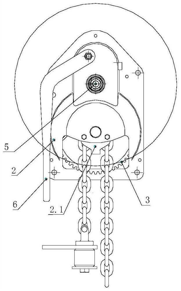
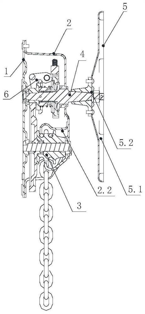
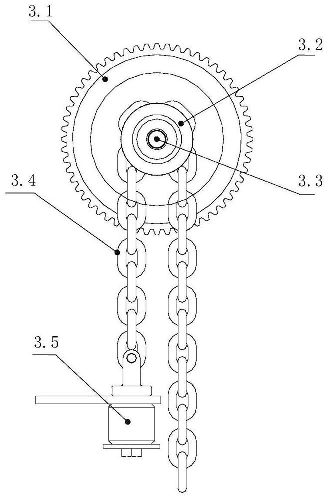
[0039] Such as Figure 1 ~ Figure 2 A hand brake for a railway freight car shown includes a base 1, a case cover 2, a winding wheel mechanism 3, a driving shaft mechanism 4, a handwheel mechanism 5 and a handle mechanism 6; the winding wheel mechanism 3 is arranged on the base 1 Below the accommodation chamber enclosed between the box cover 2, the winding chain wheel mechanism 3 is located at the lower end of the driving shaft 4.1, one end is installed on the base 1 through the bearing seat, and the other end is installed on the bearing seat of the box cover 2. The driving shaft mechanism 4 is arranged on the top of the rolling chain wheel mechanism ...


PUM


Abstract

The invention discloses a hand brake for a railway wagon. The hand brake comprises a base, a box cover, a rolling chain wheel mechanism, a driving shaft mechanism, a hand wheel mechanism and a handle mechanism. The rolling chain wheel mechanism is arranged below a containing cavity defined by the base and the box cover. The driving shaft mechanism is arranged above the rolling chain wheel mechanism and used for driving the rolling chain wheel mechanism to rotate in the forward direction or the reverse direction, one end of the driving shaft mechanism is rotationally installed on the base, and the other end of the driving shaft mechanism penetrates out of the box cover to be connected with the hand wheel mechanism; the handle mechanism is arranged above the driving shaft mechanism and used for driving the driving shaft mechanism to rotate. According to the hand brake for the railway wagon, the chain output force is large, the development requirement of heavy-duty wagons is met, the driving shaft mechanism is of an integral structure, it is guaranteed that axial movement cannot occur in the rotating process of the driving shaft, and stability and reliability are achieved.

Description

technical field [0001] The invention relates to the technical field of hand brakes, in particular to a hand brake for railway wagons. Background technique [0002] At present, the domestic railway wagons mainly use the NSW type hand brake as the hand brake device, which belongs to the ordinary capacity type hand brake of TB / T2978 "Railway wagon hand brake". With the continuous development of the heavy-duty technology of railway wagons, the output force of the NSW hand brake can no longer meet the requirements. [0003] During the application of the NSW type hand brake, when the drive shaft and other components are corroded, resulting in increased friction of the clutch friction pair, and when the vehicle's wind and hand brake act together, the clutch of the hand brake cannot be disengaged, which leads to The phenomenon that the quick release of the hand brake is not good. It is necessary to design a hand brake with medium capacity that meets the AAR standard and has good b...

Claims


Application Information

Patent Timeline
Patent Type & Authority Applications(China)
IPC IPC(8): B61H13/02B61H13/04
CPCB61H13/02B61H13/04
Inventor 曾德凉涂智文张金发刘幻云陈学良王丽娜陈祖顺陈瑞韩亚培胡文涛周乐
Owner CRRC YANGTZE GRP CO LTD
Learn More