
Automatic punching device for high-precision metal pipe fitting

A technology for metal pipe fittings and punching devices, which is applied in the field of punching metal pipe fittings. It can solve the problems that the punching device cannot adjust the clamping position, the physical injury of the staff, and the absence of a dust suction mechanism, etc., so as to prevent difficult handling and improve practicality. performance and reduce pollution

Inactive Publication Date: 2022-03-01
江苏新泰隆管件有限公司
View PDF0 Cites 2 Cited by
  • Summary
  • Abstract
  • Description
  • Claims
  • Application Information

AI Technical Summary

Problems solved by technology

[0004] The purpose of the present invention is to provide a high-precision automatic punching device for metal pipe fittings, to solve the problem that the punching device proposed in the background technology cannot adjust the clamping position, so that the device can only process pipe fittings of the same size, and the device can be reduced. practicability, and there is no dust suction mechanism, so that the dust generated during processing is likely to pollute the working environment and cause physical injury to the staff. At the same time, no scale line is set, which makes it easy to cause deviations in the punching position when punching question

Method used


Image

  • Automatic punching device for high-precision metal pipe fitting
  • Automatic punching device for high-precision metal pipe fitting
  • Automatic punching device for high-precision metal pipe fitting

Examples


Embodiment Construction

[0037] The following will clearly and completely describe the technical solutions in the embodiments of the present invention with reference to the accompanying drawings in the embodiments of the present invention. Obviously, the described embodiments are only some, not all, embodiments of the present invention. Based on the embodiments of the present invention, all other embodiments obtained by persons of ordinary skill in the art without making creative efforts belong to the protection scope of the present invention.

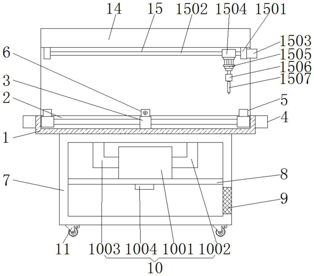
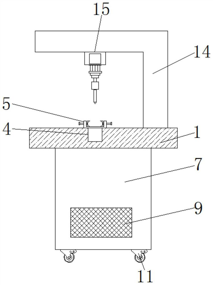
[0038] see Figure 1-6 , the present invention provides a technical solution: an automatic punching device for high-precision metal pipe fittings, according to figure 1 , Figure 4 , Figure 5 and Figure 6As shown, the upper end of the processing table 1 is provided with a groove 2, and a partition block 3 is installed in the middle of the groove 2, and a screw assembly 4 is symmetrically arranged on both sides of the partition block 3, and the screw assem...


PUM


Abstract

The high-precision metal pipe fitting automatic punching device comprises a machining table, a cabinet body and a support, a groove is formed in the upper end of the machining table, lead screw assemblies are symmetrically arranged on the two sides of a separation block, a first clamping mechanism is installed at the upper ends of the lead screw assemblies, and meanwhile a second clamping mechanism is installed at the upper end of the separation block; the cabinet body is installed at the bottom of the lower end of the machining table, the support is of an L-shaped structure, the bottom of the support is installed on the other side of the upper end of the machining table, and meanwhile the punching mechanism is installed on the inner side of the upper end of the support. The groove is conveniently divided into two small grooves with the same length, the lead screw assemblies on the two sides drive the first clamping mechanism to move, the moving distances are equal, the first clamping mechanism and the second clamping mechanism are used in cooperation, pipe fittings with different lengths can be conveniently clamped, and the practicability of the device is improved.

Description

technical field [0001] The invention relates to the technical field of punching metal pipe fittings, in particular to an automatic punching device for high-precision metal pipe fittings. Background technique [0002] As a common part, metal pipe fittings are widely used in the fields of petroleum, chemical industry, medical treatment, food, light industry, mechanical instrumentation, etc. In the process of machinery manufacturing and processing, it is often necessary to punch holes in metal pipe fittings. The production efficiency is far higher than that of drilling, and the cost is low. [0003] The existing punching device cannot adjust the clamping position, so that the device can only process pipe fittings of the same size, which reduces the practicability of the device, and is not equipped with a dust suction mechanism, so that the dust generated during processing is likely to cause damage to the working environment. Pollution, causing harm to the staff, and no scale l...

Claims


Application Information

Patent Timeline
Patent Type & Authority Applications(China)
IPC IPC(8): B21D28/34B21D28/28B21D43/00B21C51/00B08B5/04B08B15/04B01D46/10
CPCB21D28/34B21D28/28B21D43/003B21C51/00B08B5/04B08B15/04B01D46/10
Inventor 李正华夏一文夏誉容金龙
Owner 江苏新泰隆管件有限公司
Learn More