
Transmitting device, laser radar comprising same and control method

A launcher and lidar technology, which is applied in the direction of measuring device, utilization of re-radiation, re-radiation of electromagnetic waves, etc., can solve problems such as unsatisfactory, slow switching speed, difference in laser luminous power, etc., to improve performance and increase angular resolution , cost saving and volume effect

Pending Publication Date: 2022-02-25
HESAI TECH CO LTD
View PDF0 Cites 1 Cited by
  • Summary
  • Abstract
  • Description
  • Claims
  • Application Information

AI Technical Summary

Problems solved by technology

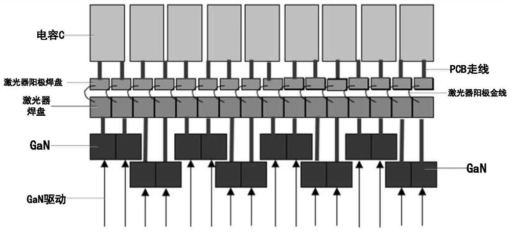
Interleaved GaN switches lead to different discharge loop lengths between two lasers (such as LAS1 and LAS2), which may cause differences in the luminous power of two lasers
Moreover, the GaN switch cannot fit well with the laser, which also has a certain impact on the response speed of the laser.
[0006] The lidars used for unmanned vehicles, logistics vehicles, and sweeping robots are usually multi-line radars, which means that the launch system has multiple lasers. Figure 2A , Figure 2B If the relative relationship shown is not arranged, the distance between each laser and its corresponding GaN switch is relatively inconsistent, resulting in different parameters such as detection accuracy of each channel or wire bundle, which is not conducive to the consistency of detection, and then affects the overall performance of the laser radar. Performance
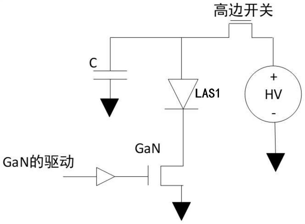
[0007] In addition, if Figure 1A As shown in , the power supply HV is provided to the line at a fixed value (for example, HV=20V), which cannot be adjusted quickly
This is because after the power supply is adjusted too fast, various capacitance and inductance effects on the line accumulate and cannot be changed as expected.
In addition, since the current high-voltage supply usually adopts DC-DC power supply or LDO (low dropout regulator), the switching speed is slow, so the light intensity of the laser cannot be adjusted quickly.
However, the external environment faced by lidar is changeable. If the same fixed light intensity is used for detection, due to the difference in reflectivity of external targets, it is easy to cause the detector to saturate or fail to detect signals, which cannot meet the needs of various scenarios.

Method used


Image

  • Transmitting device, laser radar comprising same and control method
  • Transmitting device, laser radar comprising same and control method
  • Transmitting device, laser radar comprising same and control method

Examples


Embodiment Construction

[0052] In the following, only some exemplary embodiments are briefly described. As those skilled in the art would realize, the described embodiments may be modified in various different ways, all without departing from the spirit or scope of the present invention. Accordingly, the drawings and descriptions are to be regarded as illustrative in nature and not restrictive.

[0053] In describing the present invention, it is to be understood that the terms "center", "longitudinal", "transverse", "length", "width", "thickness", "upper", "lower", "front", " Back", "Left", "Right", "Vertical", "Horizontal", "Top", "Bottom", "Inner", "Outer", "Clockwise", "Counterclockwise", etc. or The positional relationship is based on the orientation or positional relationship shown in the drawings, which is only for the convenience of describing the present invention and simplifying the description, rather than indicating or implying that the referred device or element must have a specific orie...


PUM


Abstract

The invention provides a transmitting device capable of being used for a laser radar, and the transmitting device comprises: a plurality of power supply units which are configured to input a primary voltage and output a high voltage, wherein at least two power supply units output the high voltage in a relatively different manner, and the high voltage is a voltage higher than the primary voltage; a laser unit which comprises a plurality of lasers, wherein the anode of each laser is connected to the output end of the power supply unit, so that at least two lasers are connected to different power supply units; and at least one switch device, wherein the cathodes of the partial lasers which do not share the high voltage are connected to one of the switching device, and the switching device is configured to control the on-off of a current loop formed by the corresponding power supply units, the lasers connected with the power supply units and the ground in a gating manner.

Description

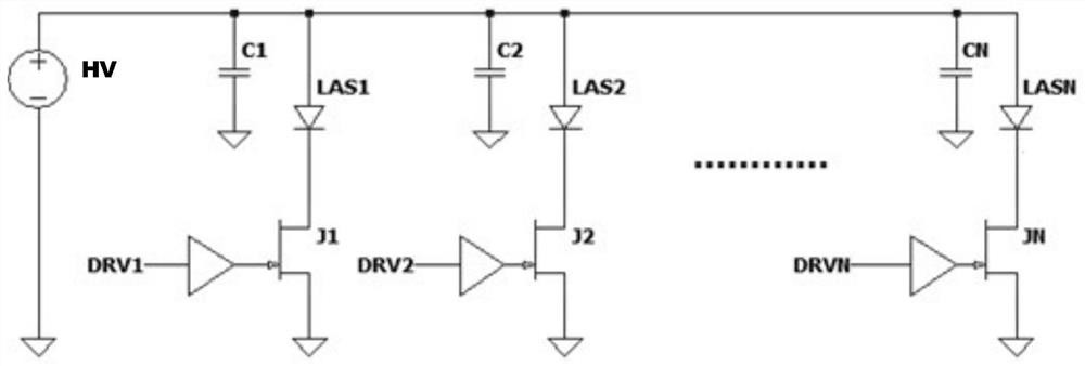
technical field [0001] The present invention generally relates to the technical field of laser radar, and in particular to a laser radar transmitting device, a control unit and a control method for controlling it. Background technique [0002] In the laser radar transmission system, the common anode is usually used to drive the laser. For example Figure 1A As shown, in the laser radar emission system in the prior art, multiple lasers LAS1...LASN share one power supply HV, and HV is continuously supplied, and the cathode of each laser is connected to a switching device (J1...JN in the figure), The light emission of the laser is determined by the gating of the switch device. Ideally, each laser is equipped with a discharge capacitor (C1...CN as shown in the figure). Due to the size of switching devices and capacitors in the prior art, multiple lasers cannot be arranged more densely, making the vertical Resolution is limited. [0003] Figure 1B It shows the power supply a...

Claims


Application Information

Patent Timeline
Patent Type & Authority Applications(China)
IPC IPC(8): G01S17/931G01S7/484
CPCG01S17/931G01S7/484
Inventor 陈杰路静静向少卿
Owner HESAI TECH CO LTD
Learn More