
A construction method of an integrated underwater cap flexible water-stop structure

A construction method, an integrated technology, applied in infrastructure engineering, construction, climate change adaptation, etc., can solve the problem of affecting the fit between the capsule and the prefabricated platform casing bottom plate, affecting the construction process of the platform, and damage to the outer wall of the capsule, etc. problems, to achieve the effect of ensuring a water-free construction environment, improving the effect of sealing and water-stopping, and avoiding the risk of water leakage

Active Publication Date: 2022-05-31
CHINA CIVIL ENG CONSTR CORP
View PDF0 Cites 0 Cited by
  • Summary
  • Abstract
  • Description
  • Claims
  • Application Information

AI Technical Summary

Problems solved by technology

[0004] However, in the existing flexible water-stop structures, rubber capsules need to be installed in the reserved grooves on the bottom plate of the prefabricated platform caps. High, if there are uneven surfaces such as honeycomb pitted surface and slight stepped surface on the finished concrete surface, it will seriously affect the fit between the capsule and the bottom plate of the prefabricated cap cover box, and then water seepage and leakage will occur, and even water stop will occur The failure will directly affect the subsequent construction process of the entire cap, and the water-stop capsule is easily scratched by animals and plants with hard shells in the water or the outer wall of the capsule is damaged by foreign objects such as welding slag remaining on the pile foundation casing that has not been cleaned. In turn, the outer wall of the capsule is damaged and the water-stopping effect is reduced.

Method used


Image

  • A construction method of an integrated underwater cap flexible water-stop structure
  • A construction method of an integrated underwater cap flexible water-stop structure
  • A construction method of an integrated underwater cap flexible water-stop structure

Examples


Embodiment Construction

[0039] Hereinafter, an embodiment of a construction method of an integrated underwater platform flexible water-stop structure of the present invention will be described with reference to the accompanying drawings. The embodiments described herein are specific embodiments of the present invention, are used to illustrate the concept of the present invention, are illustrative and exemplary, and should not be construed as limiting the embodiments of the present invention and the scope of the present invention. In addition to the embodiments described herein, those skilled in the art can also adopt other obvious technical solutions based on the contents disclosed in the claims and the description of the present application, and these technical solutions include any obvious technical solutions to the embodiments described herein. Alternative and modified technical solutions.

[0040] In the description of the present invention, it should be noted that the terms "upper", "lower", "to...


PUM


Abstract

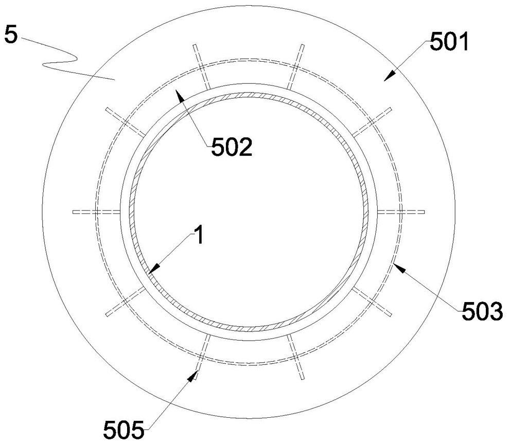
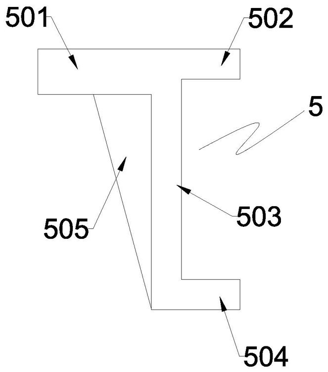
The invention discloses a construction method for an integrated underwater cap flexible water-stop structure. The water-stop structure includes a pile foundation casing and a prefabricated cap casing. The prefabricated cap casing is set on the pile foundation casing. The top of the bottom plate is welded with a shear key through the embedded parts, and the bottom of the bottom plate is embedded with a capsule tray. The capsule tray is ring-shaped and arranged around the pile foundation casing. A ring-shaped groove is formed under the prefabricated platform cover box, and a water-tight capsule is arranged in the ring-shaped groove. The water-tight capsule is in the shape of a ring. Pressurized gas or pressurized liquid, the inner and outer ring surfaces of the capsule are respectively attached to the outer wall of the pile foundation casing and the inner wall of the capsule tray, and form a vertical water-tight sealing belt. The invention has the advantages of simple structure and convenient installation. Through the setting of the capsule tray, the direct contact between the water-stop capsule and the concrete surface is avoided, and the water-free construction operation environment of the underwater cap is effectively ensured.

Description

technical field [0001] The invention relates to the technical field of underwater bearing platform construction, in particular to a construction method of an integrated underwater bearing platform flexible water-stop structure. Background technique [0002] In bridge construction, the water-stopping technology of underwater cap construction is the core of the entire project construction, and the water-stopping effect directly affects the quality and durability of concrete pouring for the cap. The traditional water-stopping process includes: pouring a certain thickness of underwater concrete on the bottom of the box to achieve the water-stopping effect; using cement mortar, epoxy resin and other materials to stop leakage and water; pouring underwater non-segregated concrete around the steel casing to stop the water. water. The above water-stopping methods are all rigid water-stopping processes, which have the advantages of strong adaptability and mature technology. [0003]...

Claims


Application Information

Patent Timeline
Patent Type & Authority Patents(China)
IPC IPC(8): E02D31/02E02D31/10E02D27/14E02D27/52
CPCE02D31/02E02D31/10E02D27/14E02D27/52Y02A30/30
Inventor 张军乐秦榕陆海强金朝
Owner CHINA CIVIL ENG CONSTR CORP
Learn More