Eureka AIR delivers breakthrough ideas for toughest innovation challenges, trusted by R&D personnel around the world.

Intelligent LOW-E glass film removing machine

A film removal machine, intelligent technology, applied to the parts of grinding machine tools, manufacturing tools, grinding drive devices, etc., can solve the problem of inconsistent film removal depth, difficult glass, and inability to meet the film removal requirements of Low-E glass with different thicknesses, etc. problem, to achieve unsatisfactory results

Active Publication Date: 2022-02-25
南京苏洋玻璃有限公司
View PDF19 Cites 0 Cited by
  • Summary
  • Abstract
  • Description
  • Claims
  • Application Information

AI Technical Summary

Problems solved by technology

[0005] The purpose of the present invention is to provide a kind of Low-E glass intelligent film removal machine, to solve the existing Low-E glass edge removal film proposed in the above background technology, which usually adopts manual film removal method, which is prone to residue and inconsistent film removal depth and the problem of irregular edges; secondly, a small number of automatic film removal methods are used. On the one hand, the existing automatic film removal equipment can only remove film for single-thickness glass, which cannot meet the film removal requirements of Low-E glass with different thicknesses. Due to the upgrade of the decoration, a lot of irregular glass appeared. The existing film removing machine uses the operating table as the glass carrier, which makes it difficult for the film removing machine to remove the film on the glass with irregular edges.

Method used


Image

  • Intelligent LOW-E glass film removing machine
  • Intelligent LOW-E glass film removing machine
  • Intelligent LOW-E glass film removing machine

Examples


Embodiment Construction

[0027] The following will clearly and completely describe the technical solutions in the embodiments of the present invention with reference to the accompanying drawings in the embodiments of the present invention. Obviously, the described embodiments are only some of the embodiments of the present invention, not all of them. Based on the embodiments of the present invention, all other embodiments obtained by persons of ordinary skill in the art without creative efforts fall within the protection scope of the present invention.

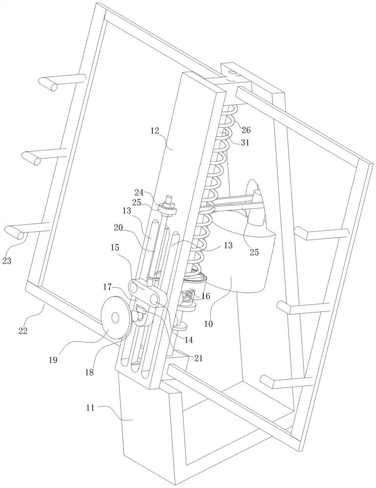
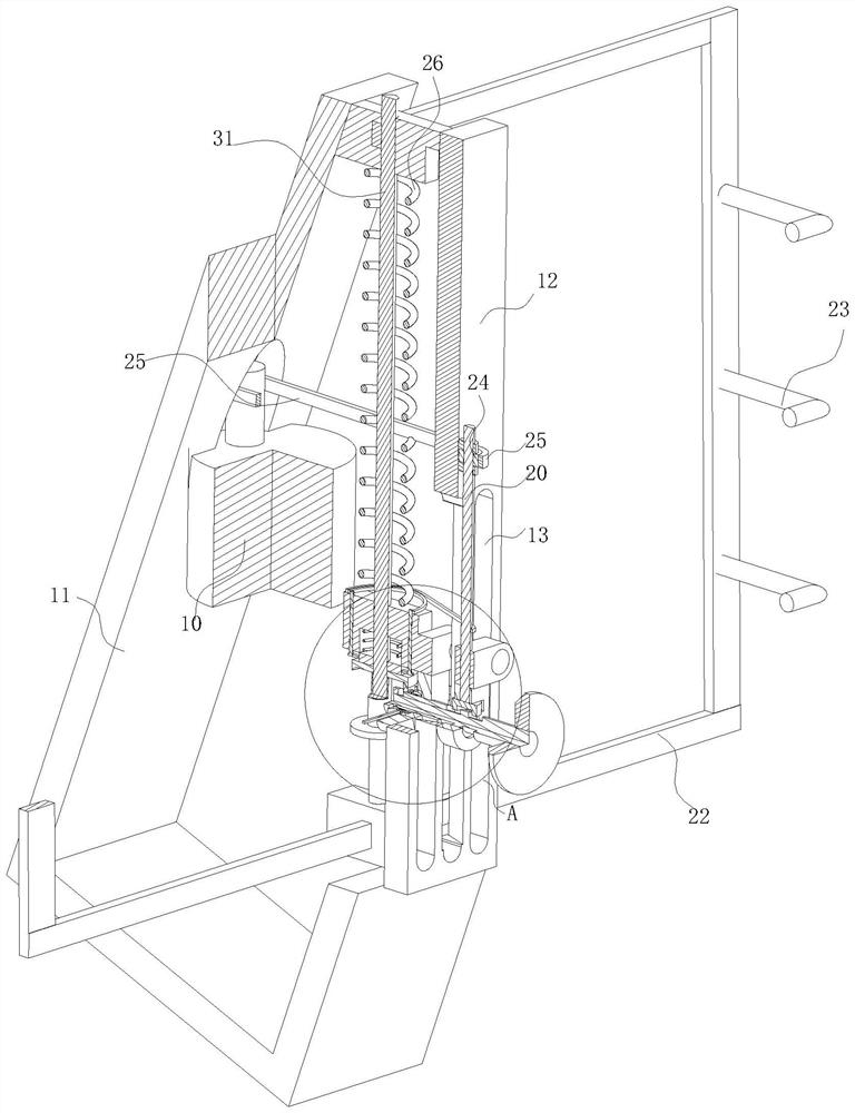
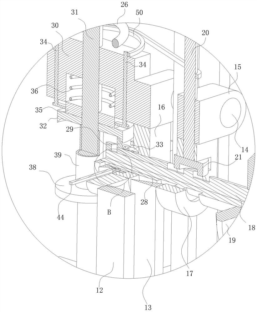
[0028] see Figure 1-8, the present invention provides a technical solution: a LOW-E glass intelligent film removal machine, including a motor 10 and an inclined base frame 11, the motor 10 is fixedly arranged on the side wall of the base frame 11, and a mounting plate is fixedly arranged on the base frame 11 12. Two symmetrical vertical sliding grooves 13 are vertically opened on the mounting plate 12, and the inner wall of each vertical sliding groo...


PUM


Abstract

The invention discloses an intelligent LOW-E glass film removing machine in the technical field of LOW-E glass film removing, wherein the intelligent LOW-E glass film removing machine comprises a motor and an inclined base frame; the motor is fixedly arranged on the side wall of the base frame, a mounting plate is fixedly arranged on the base frame, two symmetrical vertical sliding through grooves are vertically formed in the mounting plate, and a synchronous rod is vertically and slidably arranged on the inner wall of each vertical sliding through groove; and one clamping plate is fixedly arranged at the ends of the two synchronous rods located on the front side of the vertical sliding through groove, an equipment plate is fixedly arranged at the ends of the two synchronous rods located on the rear side of the vertical sliding through groove, a supporting plate is fixedly arranged at the lower end of the clamping plate, and a supporting rod is rotationally arranged on the side wall of the supporting plate. According to the invention, the problems that an existing Low-E glass edge film is easy to cause residues, the film removing depths are inconsistent and the edges are irregular due to the fact that a manual film removing mode is usually adopted in the existing Low-E glass edge film removing method are effectively solved; and secondly, many pieces of irregular glass appear, and an existing film removing machine adopts an operation table as a glass carrying table, so that the film removing machine is difficult to remove films on the glass with irregular edges.

Description

technical field [0001] The invention relates to the technical field of film removal for Low-E glass, in particular to an intelligent film removal machine for Low-E glass. Background technique [0002] Low-E glass, also known as low-emissivity glass, is a film system product composed of multiple layers of metal or other compounds coated on the glass surface. Its coating layer has the characteristics of high transmission of visible light and high reflection of mid- and far-infrared rays, which makes it have excellent heat insulation effect and good light transmission compared with ordinary glass and traditional architectural coated glass. Since the off-line Low-E glass contains materials that are easily oxidized with air, it cannot be used in a single piece, and before synthesizing the hollow, the surrounding film layer needs to be removed to avoid contact between the film layer and the sealant. After synthesizing the hollow, due to There are two layers and one layer of seala...

Claims


Application Information

Patent Timeline
IPC IPC(8): B24B27/033B24B41/06B24B47/12B24B41/00B24B47/00
CPCB24B27/033B24B41/06B24B47/12B24B41/00B24B47/00Y02W30/62
Inventor 胡凌洋子刘锋胡德明
Owner 南京苏洋玻璃有限公司
Why Eureka
Eureka Blog
Learn More