Eureka AIR delivers breakthrough ideas for toughest innovation challenges, trusted by R&D personnel around the world.

Lathe bed of laser cutting machine

A technology of laser cutting machine and machine tool, which is applied in laser welding equipment, welding equipment, metal processing equipment, etc., which can solve the problems of difficult discharge and blockage, and achieve the effect of keeping the interior clean and good smoke exhaust effect

Pending Publication Date: 2022-02-25
江阴市宸照机械有限公司
View PDF1 Cites 0 Cited by
  • Summary
  • Abstract
  • Description
  • Claims
  • Application Information

AI Technical Summary

Problems solved by technology

This application has the effect of improving the exhaust efficiency of the bed, but the reference document can only improve the exhaust efficiency of the cutting fume, and cannot prevent the splash from entering the exhaust port and causing the blockage of the exhaust port. The slag discharge pipe is blocked and difficult to discharge, so there is an urgent need for improved technology in the market to solve the above problems

Method used


Image

  • Lathe bed of laser cutting machine
  • Lathe bed of laser cutting machine
  • Lathe bed of laser cutting machine

Examples


Embodiment Construction

[0021] The following will clearly and completely describe the technical solutions in the embodiments of the present invention with reference to the accompanying drawings in the embodiments of the present invention. Obviously, the described embodiments are only some, not all, embodiments of the present invention. Based on the embodiments of the present invention, all other embodiments obtained by persons of ordinary skill in the art without creative efforts fall within the protection scope of the present invention.

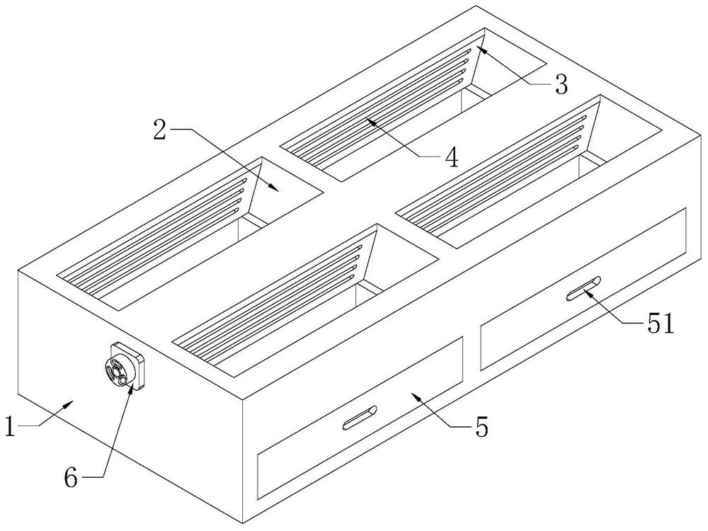
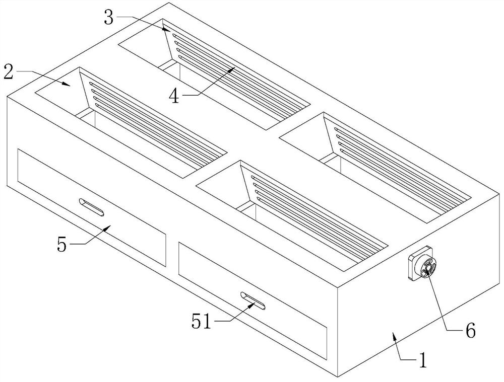
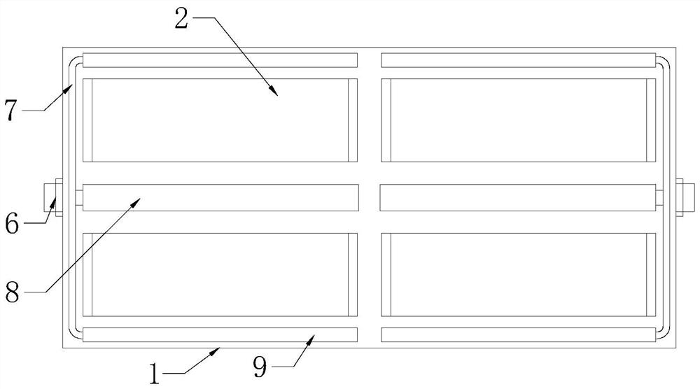
[0022] see Figure 1-3 As shown, the present invention is a laser cutting machine body, including a machine tool body 1, a collection drawer 5 and an exhaust fan 6, the top of the machine tool body 1 is provided with a top groove 2, and the front and rear sides of the top groove 2 are symmetrically provided with inclined surfaces 3. There is an air intake slot 4 on the inclined surface 3, and the air intake slot 4 is connected with the middle flue gas slot 8 and th...


PUM


Abstract

The invention discloses a lathe bed of a laser cutting machine, and relates to the technical field of laser cutting machines. The lathe bed comprises a machine tool body, a collecting drawer and an exhaust fan, wherein the top of the machine tool body is provided with a top groove, inclined surfaces are symmetrically arranged on the front side and the rear side in the top groove, air inlet notches are formed in the inclined surfaces, the air inlet notches are in through connection with a middle flue gas groove and side flue gas grooves formed in the machine tool body, the middle flue gas groove and the side flue gas grooves are in through connection with the exhaust fan fixed to the machine tool body through exhaust pipelines, and the collecting drawer is movably inserted into the portion, which is below the top groove, of the machine tool body. Through rotation of the exhaust fan, flue gas generated in the cutting process can be sucked into the middle flue gas groove and the side flue gas grooves in the machine tool body from the top groove and is finally exhausted through the exhaust pipeline, and due to the arrangement of the inclined surfaces, the situation that an air inlet groove opening is blocked by cut spatter can be effectively avoided, and the cut spatter can smoothly enter the collecting drawer to be collected.

Description

technical field [0001] The invention belongs to the technical field of laser cutting machines, in particular to a laser cutting machine body. Background technique [0002] The Chinese patent application number 202021512276.5 discloses a bed of a laser cutting machine, including a machine tool body and guide rails arranged on opposite sides of the upper end surface of the machine tool body. There is an exhaust pipe inside, and the side wall of the machine tool body close to the collection tank is provided with an air outlet. The exhaust pipe is connected to the position where the air outlet is set on the machine body. exhaust fan. This application has the effect of improving the exhaust efficiency of the bed, but the reference document can only improve the exhaust efficiency of the cutting fume, and cannot prevent the splash from entering the exhaust port and causing the blockage of the exhaust port. The slag discharge pipe is blocked and difficult to discharge. Therefore, ...

Claims


Application Information

Patent Timeline
IPC IPC(8): B23K26/142B23K26/16B23K26/38
CPCB23K26/142B23K26/16B23K26/38
Inventor 吴强
Owner 江阴市宸照机械有限公司
Why Eureka
Eureka Blog
Learn More