Modulation method and system for LED driving signal
A technology of LED drive and modulation method, which is applied in the transmission system, electromagnetic wave transmission system, electrical components, etc., can solve the problems of flat and difficult LED bandwidth, and achieve the effect of flat bandwidth and good bandwidth expansion
- Summary
- Abstract
- Description
- Claims
- Application Information
AI Technical Summary
Problems solved by technology
Method used
Image
Examples
Embodiment 1
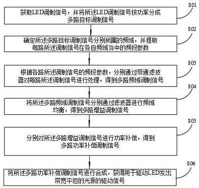
[0070] see also Figure 1 , Figure 1 The implementation flow chart of a modulation method of LED driving signal provided by the first embodiment of the invention is shown. The method specifically includes steps S01 to S06.
[0071] In step S01, the LED modulation signal is obtained, and the LED modulation signal is divided into multiple target modulation signals according to power.
[0072] Specifically, the LED modulation signal is divided into at least two target modulation signals according to the power. Among them, the more target modulation signals divided according to the power, the better the subsequent modulation effect. It is understandable that if the LED modulation signal has a wide frequency domain but is only divided into two target modulation signals, the final modulation effect will be greatly reduced.
[0073] Step S02: determine the frequency domain to which the multi-channel target modulation signal belongs, and extract the frequency band parameters of each channe...
Embodiment 2
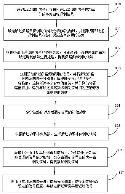
[0085] see also Figure 2 , Figure 2 The implementation flow chart of a modulation method of LED driving signal provided by the second embodiment of the invention is shown. The method specifically includes steps S10 to S17.
[0086] In step S10, the LED modulation signal is obtained and divided into multiple target modulation signals according to power.
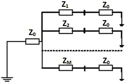
[0087] It should be noted that the LED modulation signal is divided into equal or unequal multiple power outputs through the power distributor. The power distributor is a multi port network that divides the input signal into equal or unequal power outputs. The circuit topology of any multi-section power divider is as follows: Figure 3 As shown in the figure, it can be seen that the internal resistance of signal source and load is: R S =R=Z 0 ; If it is divided into N equal parts, then Z 0 =Z 1 =…=Z M-1 , the length of each section is 。
[0088] Similarly, the design process and implementation method of unequal power distributor a...
Embodiment 3
[0134] On the other hand, the embodiment of the invention provides a modulation system of LED driving signal, which comprises:
[0135] The power division module is used to obtain the LED modulation signal and divide the LED modulation signal into multi-channel target modulation signals according to power;
[0136] A parameter extraction module for determining the frequency domain to which the multi-channel target modulation signal belongs, and extracting the frequency band parameters of each channel of the modulation signal in their respective frequency domain;
[0137] A frequency domain segmentation module for processing each channel of the modulation signal through a band-pass filter according to the frequency band parameters of each channel of the modulation signal to obtain a multi-channel frequency domain modulation signal;
[0138] An equalization module for frequency domain equalization of the multi-channel frequency domain modulation signals through a filter to obtain a ...
PUM
 Abstract
Description
Claims
Application Information
 - Generate Ideas
- Intellectual Property
- Life Sciences
- Materials
- Tech Scout
- Unparalleled Data Quality
- Higher Quality Content
- 60% Fewer Hallucinations
Browse by: Latest US Patents, China's latest patents, Technical Efficacy Thesaurus, Application Domain, Technology Topic, Popular Technical Reports.
© 2025 PatSnap. All rights reserved.Legal|Privacy policy|Modern Slavery Act Transparency Statement|Sitemap|About US| Contact US: help@patsnap.com


