
Atmospheric environment gridding monitoring system

A monitoring system and atmospheric environment technology, applied in measuring devices, analyzing gas mixtures, chemical instruments and methods, etc., can solve the problems of electrical components being easily damaged, affecting the normal use of equipment, and affecting the cooling effect of monitoring equipment, so as to avoid damage , effective monitoring, good shock absorption effect

Pending Publication Date: 2022-02-18
NANJING UNIV 5D TECH
View PDF8 Cites 2 Cited by
  • Summary
  • Abstract
  • Description
  • Claims
  • Application Information

AI Technical Summary

Problems solved by technology

[0003] However, in the process of monitoring the atmospheric environment by using the atmospheric environment grid monitoring equipment, when the monitoring equipment is subjected to external factors to generate vibration force, the electrical components installed on it are easily damaged, which will affect the monitoring effect of the monitoring equipment on the environment. The normal use of the equipment, and it does not have the function of automatically cleaning the surface of the dust-proof filter installed on the monitoring equipment. There are usually cooling holes on the testing equipment, and a dust-proof filter is installed in the cooling holes for its internal installation. Since the dust-proof filter is placed in the external environment for a long time, more dust and impurities will accumulate and adhere to the surface of the dust-proof filter, which will affect the heat dissipation effect of the monitoring equipment.

Method used


Image

  • Atmospheric environment gridding monitoring system
  • Atmospheric environment gridding monitoring system
  • Atmospheric environment gridding monitoring system

Examples


Embodiment Construction

[0023] The following will clearly and completely describe the technical solutions in the embodiments of the present invention with reference to the accompanying drawings in the embodiments of the present invention. Obviously, the described embodiments are only some, not all, embodiments of the present invention. Based on the embodiments of the present invention, all other embodiments obtained by persons of ordinary skill in the art without making creative efforts belong to the protection scope of the present invention.

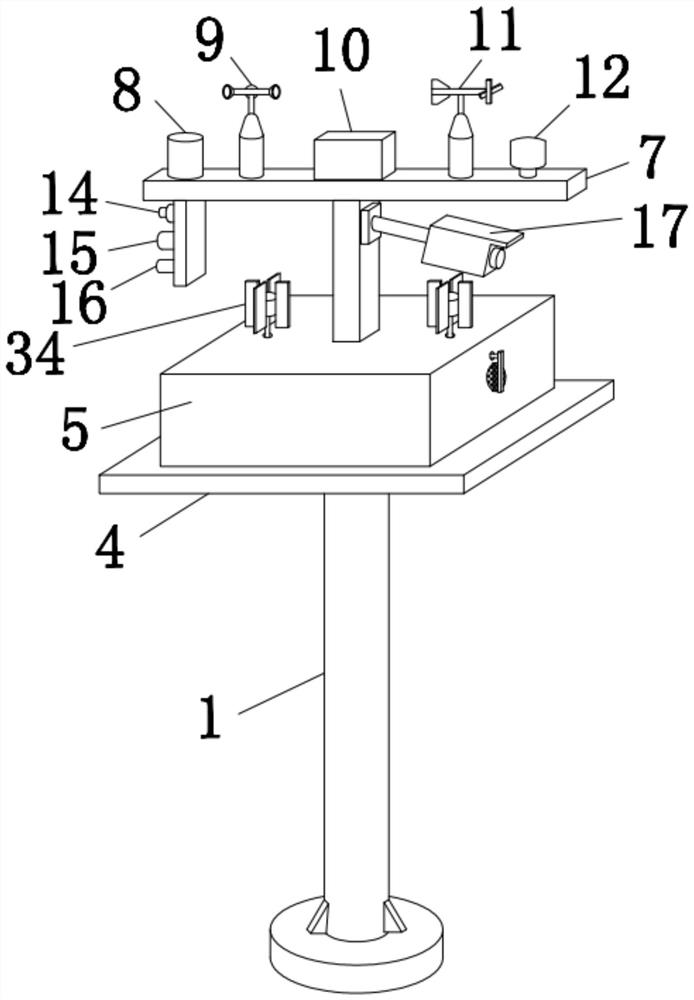
[0024] Please also refer to Figure 1-Figure 6 ,in figure 1 It is a schematic diagram of a three-dimensional structure of an embodiment of the present invention;

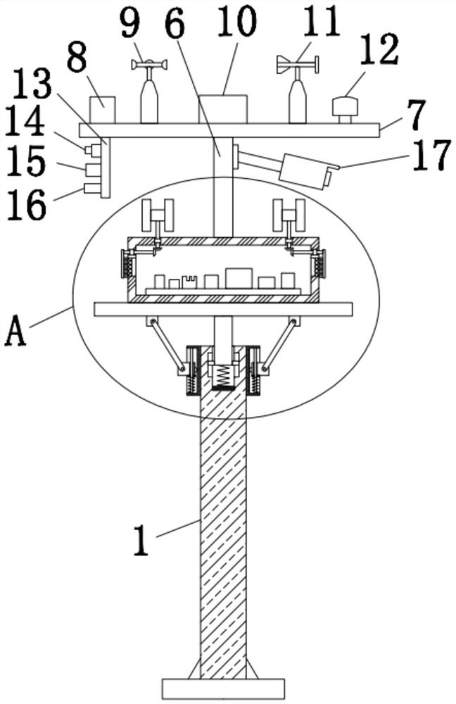
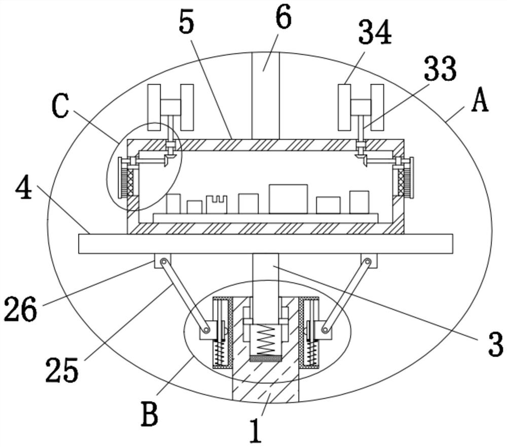
[0025] figure 2 for figure 1 Front view cross-sectional structural schematic diagram in the embodiment; image 3 for figure 2 Partial enlarged view of position A in middle; Figure 4 for image 3 Partial enlarged view of position B in middle; Figure 5 for image 3 Partial enlarged view o...


PUM


Abstract

The invention discloses an atmospheric environment gridding monitoring system. The system comprises a stand column, a mounting groove is formed in the top of the stand column, a movable column is slidably mounted in the mounting groove, the top end of the movable column extends out of the mounting groove, and a transverse plate is fixedly mounted at the top end of the movable column. Through the arrangement of s buffer assembly, vibration force borne by monitoring equipment can be effectively buffered, and a good damping effect is achieved. Equipment is prevented from being damaged by vibration force, the atmospheric environment can be monitored more effectively, by arranging a cleaning assembly, the effect of automatically cleaning the surface of a dust-proof filter screen can be achieved, the situation that the heat dissipation effect in the monitoring box is affected due to the fact that the dust-proof filter screen is blocked is avoided, and the problems that in the atmospheric environment monitoring process, when the monitoring equipment generates vibration force due to external factors, electrical elements installed on the monitoring equipment are prone to being damaged, the environment monitoring effect is affected, and the function of automatically cleaning the surface of a dustproof filter screen installed on the monitoring equipment is not achieved are solved.

Description

technical field [0001] The invention relates to the technical field of atmospheric environment monitoring, in particular to an atmospheric environment gridded monitoring system. Background technique [0002] The atmospheric environment gridded comprehensive monitoring system is mainly for the environmental management department, aiming to help solve the problem of ambient air quality monitoring in the region, provide accurate and real-time monitoring, evaluation and analysis of air pollution, and help users grasp the ambient air quality in the region , discover the characteristics of pollution, and provide technical support for the prevention and control of air pollution. As urban air pollution becomes more and more serious, urban management departments will choose to deploy air environment monitoring equipment in order to collect air quality data in various regions. The layout of lines and planes takes urban air monitoring as a whole to facilitate management and data collec...

Claims


Application Information

Patent Timeline
Patent Type & Authority Applications(China)
IPC IPC(8): G01N33/00G01N15/06G01D21/02B01D46/10B01D46/681
CPCG01N33/0009G01N33/0037G01N33/0042G01N15/06G01D21/02B01D46/10
Inventor 朱曦魏冶
Owner NANJING UNIV 5D TECH
Learn More