Downhole tubular column and hydraulic opening tool for opening sliding sleeve switch

A technology of sliding sleeve switch and downhole pipe string, which is applied in the direction of wellbore/well valve device, wellbore/well parts, earthwork drilling and production, etc. It can solve the problems such as difficult sliding sleeve combination, and achieve reliable operation and convenient use , The effect of reducing manufacturing costs

Pending Publication Date: 2022-02-18
CHINA PETROLEUM & CHEM CORP +1
View PDF5 Cites 1 Cited by
  • Summary
  • Abstract
  • Description
  • Claims
  • Application Information

AI Technical Summary

Problems solved by technology

[0008] The purpose of the present invention is to provide a downhole pipe string, which is easy to cooperate with the adapted hydraulic opening tool to open the predetermined sliding sleeve switch, so as to solve the problem that the hydraulic opening tool is not easy to combine with the predetermined sliding sleeve in the prior art Problem; at the same time, the object of the present invention is also to provide a hydraulic opening tool for opening the sliding sleeve switch, so as to accurately open the predetermined sliding sleeve switch in the above-mentioned downhole string

Method used


Image

  • Downhole tubular column and hydraulic opening tool for opening sliding sleeve switch
  • Downhole tubular column and hydraulic opening tool for opening sliding sleeve switch
  • Downhole tubular column and hydraulic opening tool for opening sliding sleeve switch

Examples


specific Embodiment 1

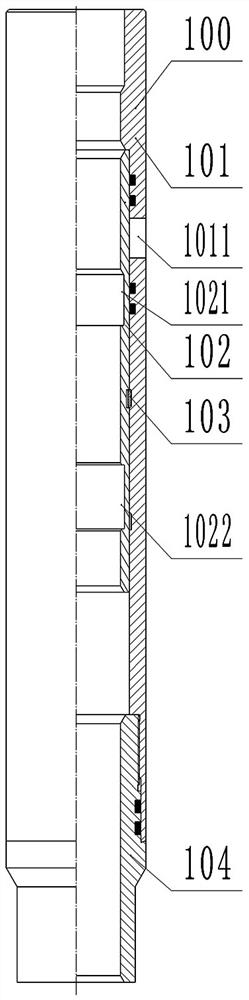
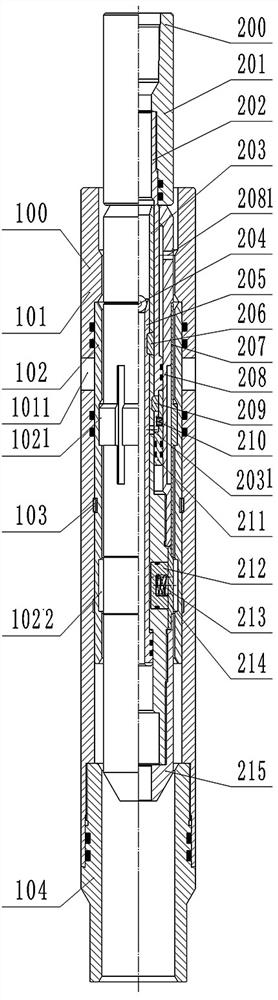
[0058] The downhole string includes the string body, which includes serially connected casings, packers, and sliding sleeve switches. The packer is used to fix the downhole string in the well, and the sliding sleeve switches are connected Corresponding to the production layer, the production of the downhole pipe string is controlled by controlling the opening and closing of the sliding sleeve switch. Under normal circumstances, when the downhole pipe string is run into the well, the sliding sleeve switch is closed. figure 2 The hydraulic opener shown controls the opening of the corresponding slide switch.

[0059] Here, there are multiple sliding sleeve switches arranged at intervals along the up and down direction, and the structures of each sliding sleeve switch are basically the same, such as figure 1 As shown, they are all composed of an outer sleeve 101, an inner sliding sleeve 102, a locking ring 103 and a lower joint 104. The outer sleeve 101 is connected to the main bo...

specific Embodiment 2

[0066] It differs from Embodiment 1 mainly in that: in Embodiment 1, the elastic locking structure arranged between the outer sleeve and the inner sleeve is a lock ring; in this embodiment, the elastic locking structure is a bow-shaped limit shrapnel, and The clips are snapped into the slots provided on the outer peripheral surface of the inner sliding sleeve, and the outer ends of the bow-shaped limiting shrapnels are set on the protrusions for matching with different slots on the inner wall of the jacket. Its structure can be referred to the bow-shaped limit shrapnel in the switch sliding sleeve in the Chinese invention patent whose authorized notification number is CN105672946B.

[0067] Of course, in other embodiments, the elastic locking structure can also adopt the anchor claw type limiting shrapnel in the switch sheath disclosed in the Chinese invention patent with the authorized notification number CN105696975B, which will not be repeated here.

Embodiment 1

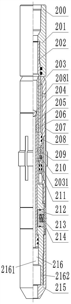
[0069] Such as Figures 2 to 7 As shown, the hydraulic opening tool 200 in this embodiment is used to run into the sliding sleeve switch 100 of the downhole string to drive the inner sliding sleeve 102 to move to the opening position to open the sliding sleeve switch.

[0070] The hydraulic closing tool 200 as a whole includes an upper joint 201 , a short connecting pipe 202 , an inner pipe 203 , an outer support pipe 208 , a ball seat 205 , a positioning ring 207 , a lifting bolt 212 , a pressure pipe 214 and a guide joint 215 .

[0071] Wherein, the external thread on the top of the connecting short pipe 202 is tightly connected with the internal thread of the upper joint 201 to form a main body of the joint, and the upper joint 201 is provided with a ring-shaped inner rim to stop and cooperate with the top end of the short connecting pipe 202 . Moreover, a sealing ring is provided between the upper joint 201 and the short connecting pipe 202 to seal the assembly gap between...


PUM


Abstract

The invention relates to a downhole tubular column and a hydraulic opening tool for opening a sliding sleeve switch, the upper and lower groove width sizes of annular positioning grooves of all the sliding sleeve switches in the underground pipe column are sequentially increased from top to bottom, and the hydraulic opening tool comprises an inner pipe assembly, a lifting lock tongue, an inward-retracting elastic piece, a positioning boss and an outward-extending elastic piece; an elastic acting force for driving the positioning boss to extend outwards is applied to the positioning boss, the positioning boss has the set up-down width size, and in the process that the hydraulic opening tool is put down through the coiled tubing, when the positioning boss extends outwards to be matched with the annular positioning groove in the corresponding sliding sleeve switch in a positioning and inserting mode, it is indicated that the hydraulic opening tool is lowered in place. In the lowering process, the positioning boss of the hydraulic opening tool is squeezed all the time before the hydraulic opening tool is not lowered in place due to the size problem until the positioning boss is clamped with the annular positioning groove of the selected sliding sleeve switch and the annular positioning groove of the selected sliding sleeve switch, it is indicated that the hydraulic opening tool is lowered in place, and therefore the selected sliding sleeve switch can be accurately turned on, and the turning-on accuracy is guaranteed.

Description

technical field [0001] The invention belongs to the field of downhole operation tools in oil and gas fields, and in particular relates to a downhole pipe string and a hydraulic opening tool for opening a sliding sleeve switch. Background technique [0002] The sliding sleeve that can be opened and closed repeatedly is one of the core tools for segmental reconstruction and layered mining of horizontal wells completed in stages. The oil flow passage is arranged on the pipe wall of the outer casing, and the inner sliding sleeve can move relative to the outer casing under the drive of the sliding sleeve switch tool, so as to open or close the oil flow passage on the outer casing. During the production process of oil and gas wells, the matching sliding sleeve opening tool can be used to open the sliding sleeve for the closed production layer, which can realize the repeated opening of the sliding sleeve of the designated production layer after repeated closing, satisfying the stra...

Claims


Application Information

Patent Timeline
IPC IPC(8): E21B34/14E21B23/10
CPCE21B34/14E21B23/10
Inventor 赵效锋曹海燕吴坤琪吴信荣董爱粉王选奎邓小伟赵国瑜
Owner CHINA PETROLEUM & CHEM CORP
Why Eureka
Try Eureka