
Electric power communication optical cable wiring method and ring network system

A wiring method and power communication technology, which are applied in optical fiber/cable installation, substation/switch layout details, optics, etc., can solve the problems of single power communication optical cable routing scheme, disconnection of the entire substation, etc., to facilitate inspection and maintenance, The effect of maintaining smooth communication

Pending Publication Date: 2022-02-15
李懿
View PDF0 Cites 0 Cited by
  • Summary
  • Abstract
  • Description
  • Claims
  • Application Information

AI Technical Summary

Problems solved by technology

[0005] Aiming at the deficiencies of the prior art, the present invention provides a power communication optical cable wiring method and a ring network system, aiming to solve the problem that the existing power communication optical cable routing scheme is single, and once the only optical cable route is damaged, the entire substation will be disconnected from the network and lost connection.

Method used


Image

  • Electric power communication optical cable wiring method and ring network system
  • Electric power communication optical cable wiring method and ring network system
  • Electric power communication optical cable wiring method and ring network system

Examples


Embodiment 1

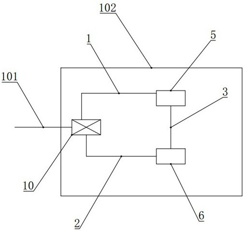
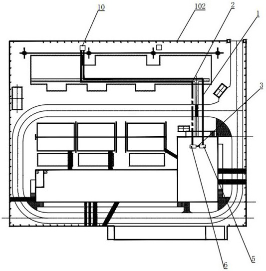
[0028] For a 220 kV substation in a certain place, the schematic diagram of the communication optical cable wiring is as follows figure 2 As shown, the equipment layout in the station area is as follows image 3 shown. The power communication optical cable is led down from the portal frame of the substation to the optical cable splicing box 10 to form an inbound optical cable 101, and the optical cable splicing box 10 is located in the floor-standing residual cable box. In the secondary equipment room, select two empty screen cabinets equipped with ODF optical fiber distribution frames, and set one of the empty screen cabinets as communication optical distribution screen 5, and the other empty screen cabinet as protection optical distribution screen 6, and enter the station After the optical cable 101 is fused by the optical cable splice box 10, the 36-core guiding optical cable is divided into two parts: the first guiding optical cable 1, the number of optical fibers of whi...

Embodiment 2

[0030] In a 220 kV substation in a certain place, the communication optical cable wiring is as follows Figure 4 As shown, the equipment layout in the station area is as follows Figure 5 shown. In terms of the access method, due to the limited layout space of the substation, the incoming optical cable 101 in this substation is not led down from the portal frame to the floor-type residual cable box, but directly to the optical cable connection box after passing through the transfer box at the landing point of the submarine cable. 10. The optical cable splicing box 10 is located on the cable mezzanine of the power distribution device building of the substation. In the secondary equipment room, select two empty screen cabinets equipped with ODF optical fiber distribution frames, and set one of the empty screen cabinets as communication optical distribution screen 5, and the other empty screen cabinet as protection optical distribution screen 6, and enter the station After the ...


PUM


Abstract

The invention discloses an electric power communication optical cable wiring method and a ring network system. The method comprises the following steps of 1, arranging an optical cable splice closure, leading an electric power communication optical cable into the optical cable splice closure from a transformer substation, and forming an incoming optical cable; 2, selecting empty screen cabinets with ODF optical fiber distribution frames on two sides in a secondary equipment room, setting one empty screen cabinet as a communication light distribution screen, and setting the other empty screen cabinet as a protection light distribution screen; 3, laying an optical cable from the communication light distribution screen and connecting the optical cable to the optical cable splice closure to form a first guide optical cable, and laying an optical cable from the protection light distribution screen and connecting the optical cable to the optical cable splice closure to form a second guide optical cable; and 4, a third guide optical cable used for connecting the two cabinets being laid between the communication light distribution screen and the protection light distribution screen. The ring network system comprises an optical cable splice closure, a communication light distribution screen and a protection light distribution screen which are connected with one another through guide optical cables to form an annular loop. According to the method, the risk of transmission channel shutdown caused by fiber breakage of the optical cable is eliminated.

Description

technical field [0001] The invention relates to the technical field of power communication, in particular to a power communication optical cable wiring method and a ring network system. Background technique [0002] The power communication network is like the nervous system of a power company, directly responsible for the transmission and feedback of important information such as power grid dispatching control, equipment inspection, infrastructure construction, marketing, customer service, and administrative management. link. Due to the advantages of light unit weight, large transmission capacity, small process attenuation, strong anti-interference ability, and good confidentiality, optical fiber communication has replaced cable communication, high-voltage power line carrier communication and microwave relay communication, etc., and has become the main communication network of modern power grids. form. [0003] Outside the substation, the power communication optical cable ...

Claims


Application Information

Patent Timeline
Patent Type & Authority Applications(China)
IPC IPC(8): G02B6/46G02B6/44H02B1/20
CPCG02B6/46G02B6/444G02B6/4446G02B6/4452H02B1/202
Inventor 李懿吴侃侃陈北海
Owner 李懿
Learn More