
Elevator

A technology of elevators, drives, used in the direction of elevators in buildings, transport and packaging, hoists

Inactive Publication Date: 2007-01-31
MITSUBISHI ELECTRIC CORP
View PDF8 Cites 0 Cited by
  • Summary
  • Abstract
  • Description
  • Claims
  • Application Information

AI Technical Summary

Problems solved by technology

[0003] In addition, since the conventional car is supported at one place by the upper beam provided on the upper part of the car, there is a problem that the vertical dimension of the hoistway corresponding to the hanging part must be ensured.

Method used


Image

  • Elevator
  • Elevator
  • Elevator

Examples


Embodiment Construction

[0017] In order to explain the present invention in more detail, it will be described with reference to the accompanying drawings.

[0018] [Embodiment 1]

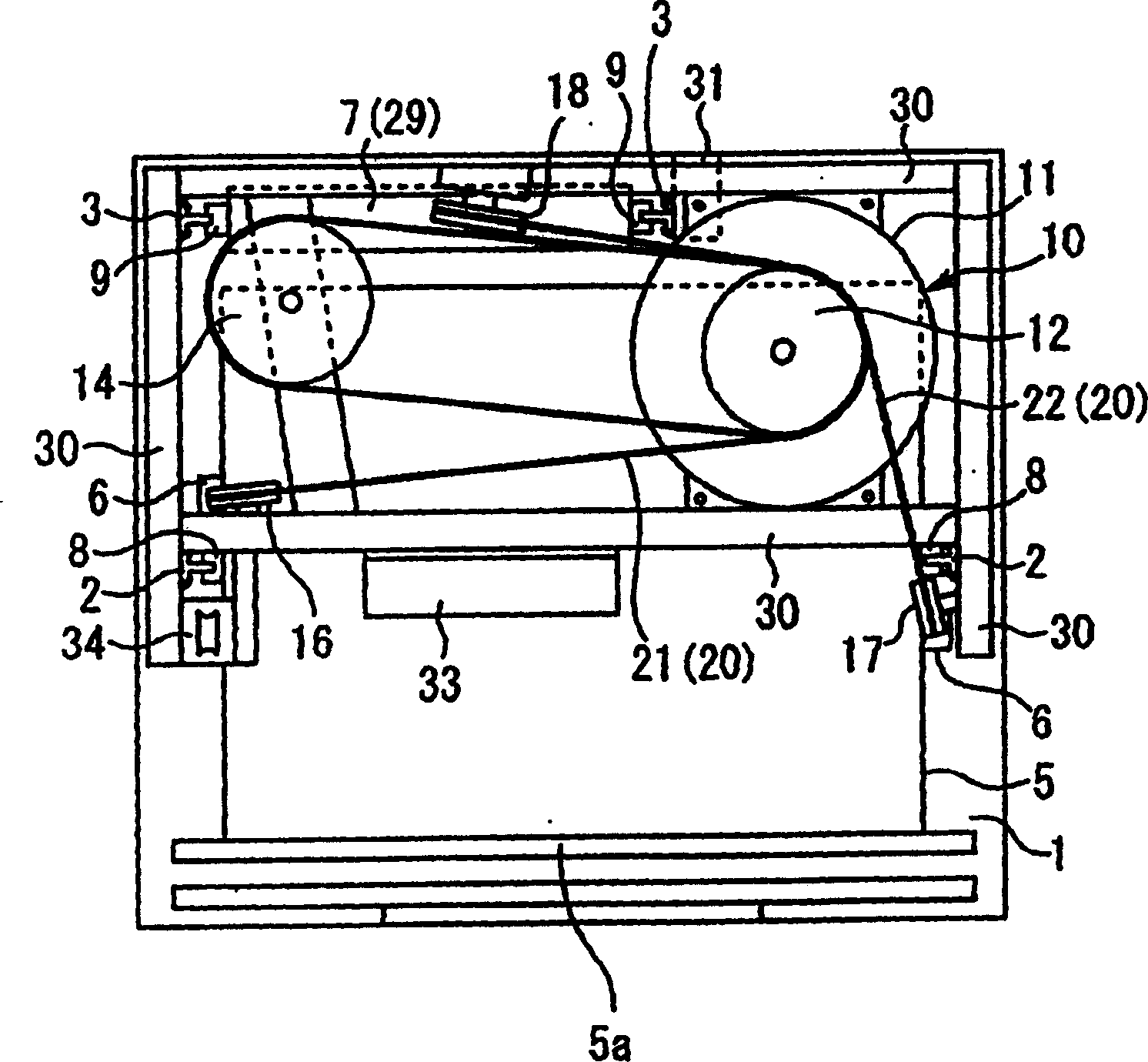
[0019] figure 1 , figure 2 It is a figure which shows the arrangement example of the elevator apparatus without a machine room type in Embodiment 1 of this invention, figure 1 It is a top view of the elevator installation from above, figure 2 It is a partial elevation view of the elevator device viewed from the horizontal direction, and is a conceptual diagram showing the main parts of the elevator device.

[0020] In the figure, a pair of main (car) guide rails 2 and another pair of auxiliary (counterweight) guide rails 3 supported by guide rail brackets 4 installed on the wall of the elevator passage 1 are arranged in the elevator passage 1 . The car 5 is guided by the main guide rail 2 and ascends and descends in the elevator passage 1, and the counterweight 7 is guided by the auxiliary guide rail 3 and ascends an...


PUM


Abstract

The rotating axle with a intermediate wheel of drive pully is fitted plumply. The main rope has parallel two routes and respectively independent first rope and second rope, their one end is counted with weight which is used to conduct direction change through diviation wheel, and the other end is conducted direction change respectively using the first car through one diviation wheel and the secondarg car through the other diviation wheel.

Description

technical field [0001] The present invention relates to an elevator apparatus in which a driving device is disposed in an upper portion of a hoistway. Background technique [0002] In recent years, due to restrictions on the installation space of elevators due to restrictions on the appearance of buildings and heights, elevators that do not require a machine room, for example, elevators that install drive devices and control panels in the elevator passage without installing a machine room have become popular. stand up. Therefore, it is necessary to effectively utilize the narrow space in the hoistway to properly configure the elevator equipment such as the drive device and the control panel. The device is arranged in the upper part of the elevator passage in the 1:1 traction mode elevator. However, in the conventional elevator apparatus, the winding angle of the main rope to the driving sheave is small, and as a device for ensuring the frictional force between the driving ...

Claims


Application Information

Patent Timeline
IPC IPC(8): B66B11/08B66B7/06B66B11/00B66B15/04
CPCB66B15/04B66B11/0045B66B11/008
Inventor 滨口修喜
Owner MITSUBISHI ELECTRIC CORP
Learn More