Coal fire treatment and utilization system and method based on carbon dioxide process and modular design

A modular design, carbon dioxide technology, applied in lighting and heating equipment, fire prevention, mining equipment, etc., can solve the problems of large engineering volume, large water consumption, high cost, etc., achieve moderate temperature, suppress coal fire regeneration, and be easy to module effect

Pending Publication Date: 2022-02-15
CHINA THREE GORGES CORPORATION +1
View PDF5 Cites 1 Cited by
  • Summary
  • Abstract
  • Description
  • Claims
  • Application Information

AI Technical Summary

Problems solved by technology

However, this type of method has the problems of large water consumption, large engineering volume and high cost.

Method used


Image

  • Coal fire treatment and utilization system and method based on carbon dioxide process and modular design
  • Coal fire treatment and utilization system and method based on carbon dioxide process and modular design
  • Coal fire treatment and utilization system and method based on carbon dioxide process and modular design

Examples


Embodiment 1

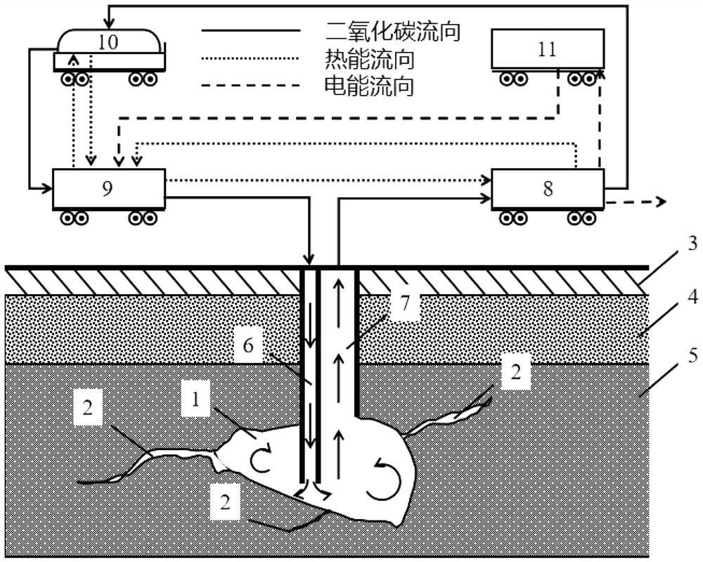
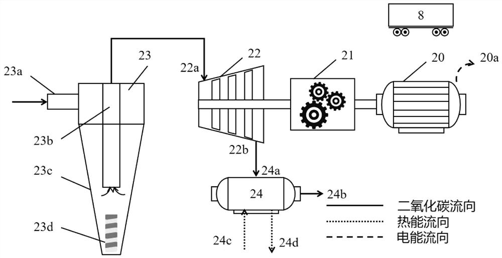
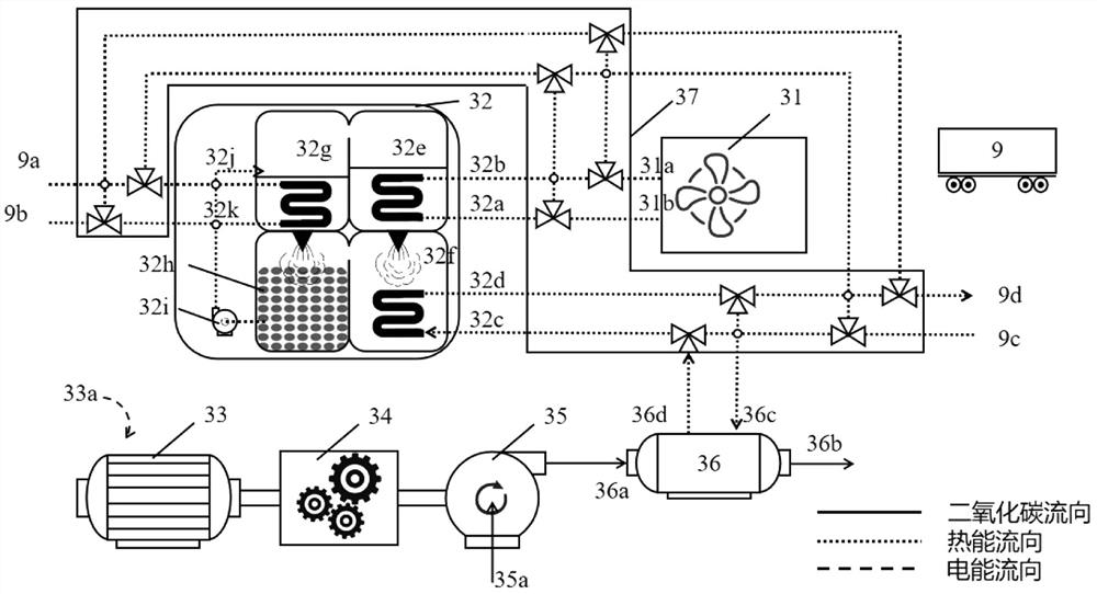
[0057] see Figure 1-4 , a coal fire treatment and utilization system based on carbon dioxide technology and modular design, which includes a heat source system for providing heat sources, and the heat source system is connected to a mobile power generation system for power generation; the heat source system includes an underground coal fire core area 1. The underground coal fire core area 1 is located inside the coal seam 5. A gaseous carbon dioxide collection well 7 is installed inside the coal seam 5 and communicated with the underground coal fire core area 1. The side of the gaseous carbon dioxide collection well 7 is provided with a carbon dioxide transmission line. Piping 6 ; the mobile power generation system includes four parts: a mobile expansion part 8 , a mobile booster part 9 , a mobile liquid carbon dioxide storage tank 10 and a mobile electric energy storage part 11 . By adopting the above-mentioned system, the side reaction of the carbon dioxide medium in the sp...

Embodiment 2

[0065] A coal fire treatment and utilization system based on carbon dioxide technology and modular design. In the treatment process, there are mainly three mass and energy flows: carbon dioxide flow, thermal energy flow and electric energy flow. The carbon dioxide fluid passes through the mobile expansion part 8, the mobile liquid carbon dioxide storage tank 10, the mobile booster part 9, the high temperature and high pressure liquid carbon dioxide transmission pipe 6, the coal fire core area 1, the gaseous carbon dioxide collection well 7, the mobile The expansion part 8 is sequentially connected to form a system to complete the thermodynamic cycle of carbon dioxide power generation.

[0066] Further, based on the operation method of the coal fire treatment and utilization system based on carbon dioxide technology and modular design, the system starts to be put into operation. In the heat source system, the underground space formed by the core area 1 of the underground coal fi...


PUM


Abstract

The invention relates to a coal fire treatment and utilization system and method based on a carbon dioxide process and modular design, and the system comprises a heat source system for providing a heat source, and the heat source system is connected with a mobile power generation system for power generation; the heat source system comprises an underground coal fire core area, the underground coal fire core area is located in the coal seam, a gaseous carbon dioxide collecting well is arranged at the position, communicated with the underground coal fire core area, in the coal seam, and a carbon dioxide conveying and distributing pipe is arranged on the side edge of the gaseous carbon dioxide collecting well; the movable type power generation system comprises a movable type expansion part, a movable type pressure boosting part, a movable type liquid carbon dioxide storage tank and a movable type electric energy storage part. The side reaction of a carbon dioxide medium when the temperature is lower than 500 DEG C in the underground coal fire spontaneous combustion process is fully considered, and the comprehensive functions of underground coal fire treatment, carbon dioxide capture, modularization mobility, coal fire waste heat utilization and the like are achieved.

Description

technical field [0001] The invention belongs to the field of coal mine security, in particular to a coal fire treatment and utilization system and method based on carbon dioxide technology and modular design. Background technique [0002] China is a big coal country, and 70% of our industry depends on coal resources. With the goal of carbon peaking and carbon neutrality proposed, the low emission and refined utilization of coal resources will be particularly important. Coal fire disasters occur widely in major coal producing areas around the world, which not only bring huge resource loss to our country and even the world, but also cause serious damage to the atmospheric environment. According to reports, my country directly loses 13.6 million tons of coal resources due to coal fires every year, and indirect losses of 200 million tons of coal resources due to inability to mine, and causes more than 35 million tons of carbon dioxide emissions. [0003] The existing treatment...

Claims


Application Information

Patent Timeline
IPC IPC(8): E21F5/00F01K25/10F01D15/10F25B15/02
CPCE21F5/00F01K25/103F01D15/10F25B15/02Y02A30/27
Inventor 蔺新星尹立坤谢宁宁刘延超苏文
Owner CHINA THREE GORGES CORPORATION
Why Eureka
Try Eureka