Construction method of laminated slab and building structure

A construction method and building structure technology, applied to building components, building structures, on-site preparation of building components, etc., can solve problems such as the difficulty of binding reinforced beams, fatigue damage of extended steel bars, poor overall performance of floors, etc., to achieve Ensure the convenience of construction, ensure the efficiency of construction, and improve the effect of construction quality

Active Publication Date: 2022-02-15
中冶城市投资控股有限公司
View PDF2 Cites 1 Cited by
  • Summary
  • Abstract
  • Description
  • Claims
  • Application Information

AI Technical Summary

Problems solved by technology

[0002]In the installation process of truss reinforced concrete laminated slabs of prefabricated residential buildings, the end faces of laminated slabs are usually provided with outstretched steel bars, and the first laminated slab is a wooden formwork For the support system, if the laminated slab is hoisted first and then the beam reinforcement is bound, the overhanging reinforcement will interfere with the beam reinforcement, which will greatly increase the difficulty of binding the beam reinforcement; if the beam reinforcement is bound first and then the laminated slab is hoisted, the overhang of the Reinforcement still interferes with the beam reinforcement. Usually, the extended reinforcement is bent to avoid interference with the beam reinforcement. However, bending the extended reinforcement not only complicates the construction process, but also causes the bending of the extended reinforcement. There will be problems of fatigue failure, resulting in poor overall performance of the poured slab

Method used


Image

  • Construction method of laminated slab and building structure
  • Construction method of laminated slab and building structure
  • Construction method of laminated slab and building structure

Examples


Embodiment Construction

[0026] In order to make the technical problems solved by the present invention, the technical solutions adopted and the technical effects achieved clearer, the technical solutions of the present invention will be further described below in conjunction with the accompanying drawings and through specific implementation methods.

[0027] In the description of the present invention, unless otherwise clearly specified and limited, the terms "connected", "connected" and "fixed" should be understood in a broad sense, for example, it can be a fixed connection, a detachable connection, or an integrated ; It can be a mechanical connection or an electrical connection; it can be a direct connection or an indirect connection through an intermediary, and it can be the internal communication of two components or the interaction relationship between two components. Those of ordinary skill in the art can understand the specific meanings of the above terms in the present invention in specific si...


PUM


Abstract

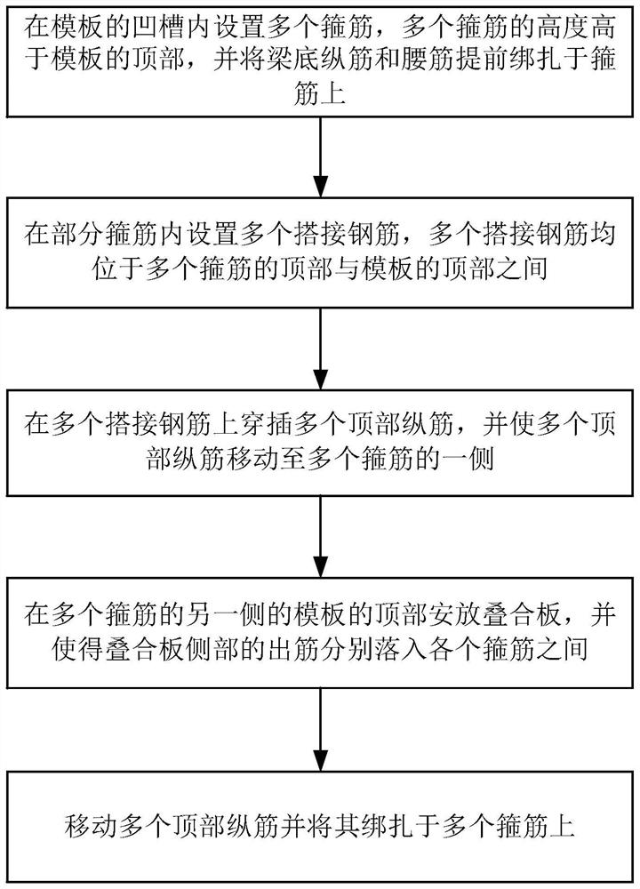
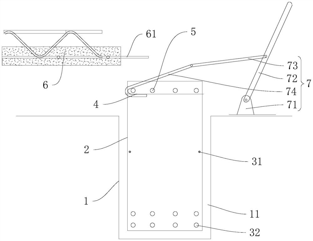
The invention discloses a construction method of a laminated slab and a building structure and relates to the technical field of building engineering. The construction method of the laminated slab comprises steps that a plurality of stirrups are arranged in a groove of a formwork, and the stirrups are higher than the top of the formwork; a plurality of lap joint steel bars are arranged in part of the stirrups, and the lap joint steel bars are all located between the tops of the stirrups and the top of the formwork; a plurality of top longitudinal bars are inserted into the multiple lap joint steel bars in a penetrating mode, and the multiple top longitudinal bars are moved to one side of the multiple stirrups; a laminated slab is placed on the top of the formwork on the other side of the multiple stirrups, and the outwards-extending steel bars on the side of the laminated slab fall into the positions between the stirrups; and the multiple top longitudinal bars are moved and bound to the multiple stirrups. According to the construction method of the laminated slab, it can be guaranteed that the laminated slab is rapidly installed when the overhanging steel bars are in the normal state, and overall reliability after floor slab pouring is completed is guaranteed.

Description

technical field [0001] The invention relates to the technical field of construction engineering, in particular to a construction method and a building structure of a laminated board. Background technique [0002] In the installation process of the truss reinforced concrete laminated slabs of prefabricated residential buildings, the end faces of the laminated slabs are usually provided with outstretched steel bars, and the first laminated slab is a wooden formwork support system. The stretching reinforcement will interfere with the beam reinforcement, which will greatly increase the difficulty of binding the beam reinforcement; if the beam reinforcement is bound first and then the laminated slab is hoisted, the protruding reinforcement of the composite slab will still interfere with the beam reinforcement. Bending is performed to avoid interference with the beam reinforcement, but bending the extension reinforcement not only complicates the construction process, but also caus...

Claims


Application Information

Patent Timeline
Patent Type & Authority Applications(China)
IPC IPC(8): E04B5/17E04B5/18E04C5/06E04C5/18E04G11/46E04G21/12E04G21/18
CPCE04B5/17E04B5/18E04C5/0627E04C5/18E04G11/46E04G21/12E04G21/18E04B2005/176
Inventor 冯唐彪黄嘉熙韦廷实汤皓文孔繁禧谢熊法包坤亮
Owner 中冶城市投资控股有限公司
Why Eureka
Try Eureka