Ultralow-temperature liquid hydrogen storage pressure vessel interlayer space vacuumizing method and device

A pressure vessel, ultra-low temperature technology, applied in the field of vacuuming, can solve the problems of long-term vacuuming, increase production cost, power consumption, etc., to achieve the effect of ensuring vacuum degree, improving reliability, reducing time and energy consumption

Inactive Publication Date: 2022-02-11
JIANGYIN FUREN HIGH TECH
View PDF0 Cites 0 Cited by
  • Summary
  • Abstract
  • Description
  • Claims
  • Application Information

AI Technical Summary

Problems solved by technology

[0008] Second, high energy consumption
Due to the low efficiency and high energy consumption of the vacuum pump in the later stage, it takes a long time to vacuum, which consumes a lot of electricity, and it needs to be monitored by a row of personnel for a long time, which increases the production cost

Method used


Image

  • Ultralow-temperature liquid hydrogen storage pressure vessel interlayer space vacuumizing method and device
  • Ultralow-temperature liquid hydrogen storage pressure vessel interlayer space vacuumizing method and device
  • Ultralow-temperature liquid hydrogen storage pressure vessel interlayer space vacuumizing method and device

Examples


Embodiment 1

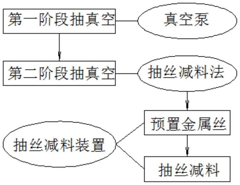
[0057] Such as Figures 1 to 7 Shown is an embodiment of a method for vacuuming the interlayer space of an ultra-low temperature liquid hydrogen storage pressure vessel according to the present invention, which sequentially includes the first stage of vacuuming the interior of the interlayer space 4 of the ultra-low temperature liquid hydrogen storage pressure vessel 1 by using a vacuum pump and adopting vacuum pumping. The second-stage vacuuming of the interlayer space of the ultra-low temperature liquid hydrogen storage pressure vessel by the wire-reducing method; in the second-stage vacuuming, the vacuuming steps of the wire-reducing method are as follows:

[0058] (1) Pre-installed metal wire: in the manufacturing stage of the ultra-low temperature liquid hydrogen storage pressure vessel 1, an ultra-long metal wire 5 with a certain volume and weight is placed in the interlayer space 4 of the ultra-low temperature liquid hydrogen storage pressure vessel 1 in advance, At the...

Embodiment 2

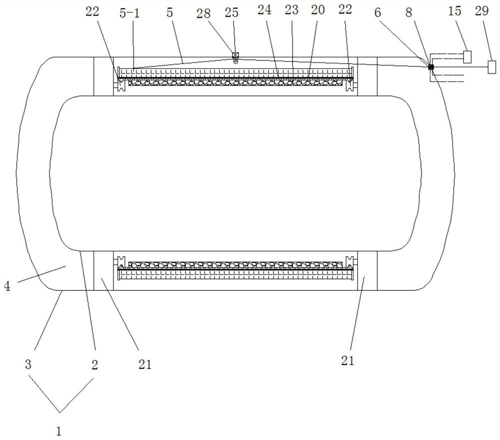
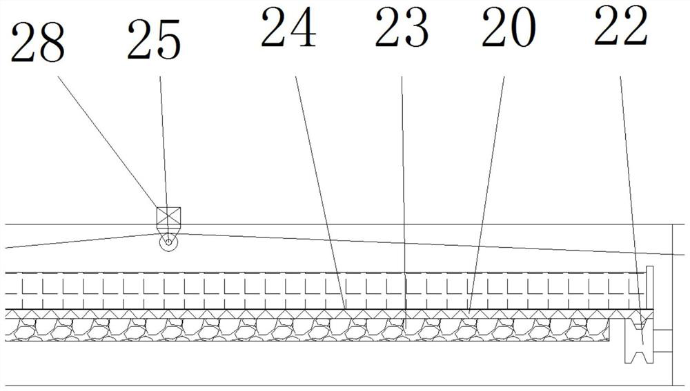
[0085] A device for vacuuming the interlayer space of an ultra-low temperature liquid hydrogen storage pressure vessel, comprising a metal wire 5 built into the interlayer space 4 of the ultra-low temperature liquid hydrogen storage pressure vessel 1 during the manufacturing stage of the ultra-low temperature liquid hydrogen storage pressure vessel 1, and a metal wire 5 arranged in the interlayer space 4 of the ultra-low temperature liquid hydrogen storage pressure vessel 1. The micro-perforation 6 on the outer container 3 of the ultra-low temperature liquid hydrogen storage pressure vessel 1, the wire drawing device 29 arranged outside the outer container 3, and one end of the metal wire 5 passes through the interlayer space 4. After passing through the micro-perforation 6, it protrudes to the outside of the tank wall of the outer container 3, and an interference sealing fit is formed between the metal wire 5 and the micro-perforation 6 by wire drawing, and the metal wire 5 pro...


PUM


Abstract

The invention discloses an ultralow-temperature liquid hydrogen storage pressure vessel interlayer space vacuumizing method and device. The vacuumizing method adopts a wire drawing material reducing vacuumizing method and comprises the following steps that: (1), a metal wire is preset: in the manufacturing stage of the ultralow-temperature liquid hydrogen storage pressure vessel, an ultra-long metal wire with a certain volume and weight is put in an interlayer space of the ultralow-temperature liquid hydrogen storage pressure vessel in advance, meanwhile, a micro-perforated hole is formed in the tank wall of an outer container of the ultralow-temperature liquid hydrogen storage pressure container, one end of the metal wire penetrates through the micro-perforated hole from the interior of the interlayer space and then extends out of the tank wall of the outer container, and the metal wire and the micro-perforated hole are in interference sealing fit through wiredrawing; and (2), wire drawing and material reducing are conducted, specifically, the metal wires are pulled from the outside, the metal wires preset in the interlayer space are gradually drawn out in a wire drawing mode, and after wire drawing and material reducing are conducted, the micro-perforated holes where the metal wires penetrate are sealed from the outside through a surfacing method. The vacuum pumping efficiency can be improved, the vacuum pumping energy consumption is reduced, and the vacuum degree of the interlayer space of the ultralow-temperature liquid hydrogen storage pressure container is improved.

Description

technical field [0001] The invention relates to the technical field of vacuuming, in particular to a method and device for vacuuming the interlayer space of an ultra-low temperature liquid hydrogen storage pressure vessel. Background technique [0002] The ultra-low temperature liquid hydrogen storage pressure vessel is a cryogenic pressure vessel used to store ultra-low temperature liquefied hydrogen. It adopts a double-layer structure, including an inner container and an outer container. A vacuum interlayer space is formed between the inner container and the outer container to isolate the transfer of external heat. , to ensure the safety of the cryogenic liquefied gas in the inner container. In order to improve the thermal insulation performance, thermal insulation materials are usually wound on the inner container body to reduce heat conduction, convection and radiation, so as to achieve the purpose of thermal insulation and storage of cryogenic liquids. The interlayer v...

Claims


Application Information

Patent Timeline
Patent Type & Authority Applications(China)
IPC IPC(8): F17C3/04F17C3/08F17C13/00F17C13/12F16J15/43
CPCF17C3/085F17C3/04F17C13/001F17C13/12F16J15/43F17C2203/0308F17C2203/0304F17C2203/0391F17C2203/0345F17C2203/0656F17C2203/0663F17C2209/2154F17C2209/238F17C2221/012F17C2260/042Y02E60/32
Inventor 计徐伟陈凯罗展鹏徐兴宝朱明国梁荣桂
Owner JIANGYIN FUREN HIGH TECH
Why Eureka
Try Eureka