
Automatic clamping equipment and automatic part clamping system

A clamping component and clamping technology, which is applied in the directions of packaging, liquid bottling, conveyor objects, etc., can solve the problems of high repeatability, high labor intensity, operator injury, etc., to avoid danger, reduce labor intensity, The effect of increasing the degree of automation

Pending Publication Date: 2022-02-11
ZHUHAI GREE INTELLIGENT EQUIP CO LTD +1
View PDF5 Cites 0 Cited by
  • Summary
  • Abstract
  • Description
  • Claims
  • Application Information

AI Technical Summary

Problems solved by technology

Using this method to limit the parts is not only highly repeatable, but also labor-intensive for the operator, and it is also dangerous. The process of liquid injection and suction is easy to cause injury to the operator.

Method used


Image

  • Automatic clamping equipment and automatic part clamping system
  • Automatic clamping equipment and automatic part clamping system
  • Automatic clamping equipment and automatic part clamping system

Examples


Embodiment Construction

[0061] The technical solutions of the present invention will be clearly and completely described below in conjunction with the accompanying drawings. Apparently, the described embodiments are some of the embodiments of the present invention, but not all of them. Based on the embodiments of the present invention, all other embodiments obtained by persons of ordinary skill in the art without making creative efforts belong to the protection scope of the present invention.

[0062] In the description of the present invention, it should be noted that the terms "center", "upper", "lower", "left", "right", "vertical", "horizontal", "inner", "outer" etc. The indicated orientation or positional relationship is based on the orientation or positional relationship shown in the drawings, and is only for the convenience of describing the present invention and simplifying the description, rather than indicating or implying that the referred device or element must have a specific orientation, ...


PUM


Abstract

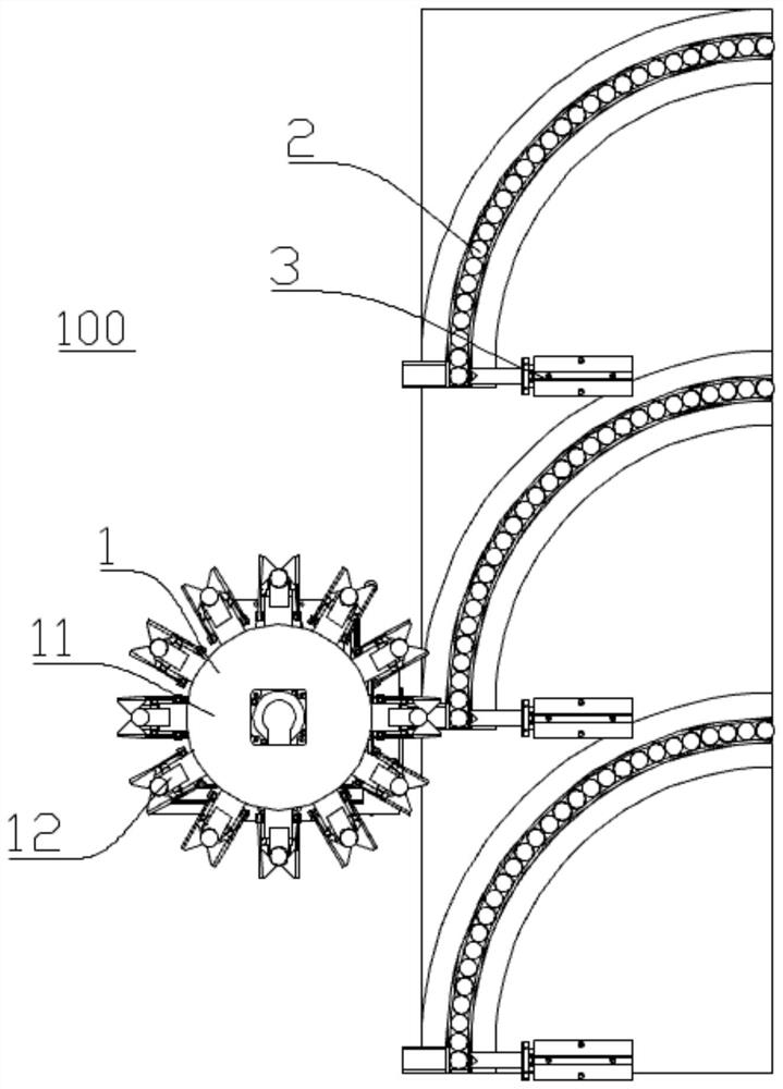
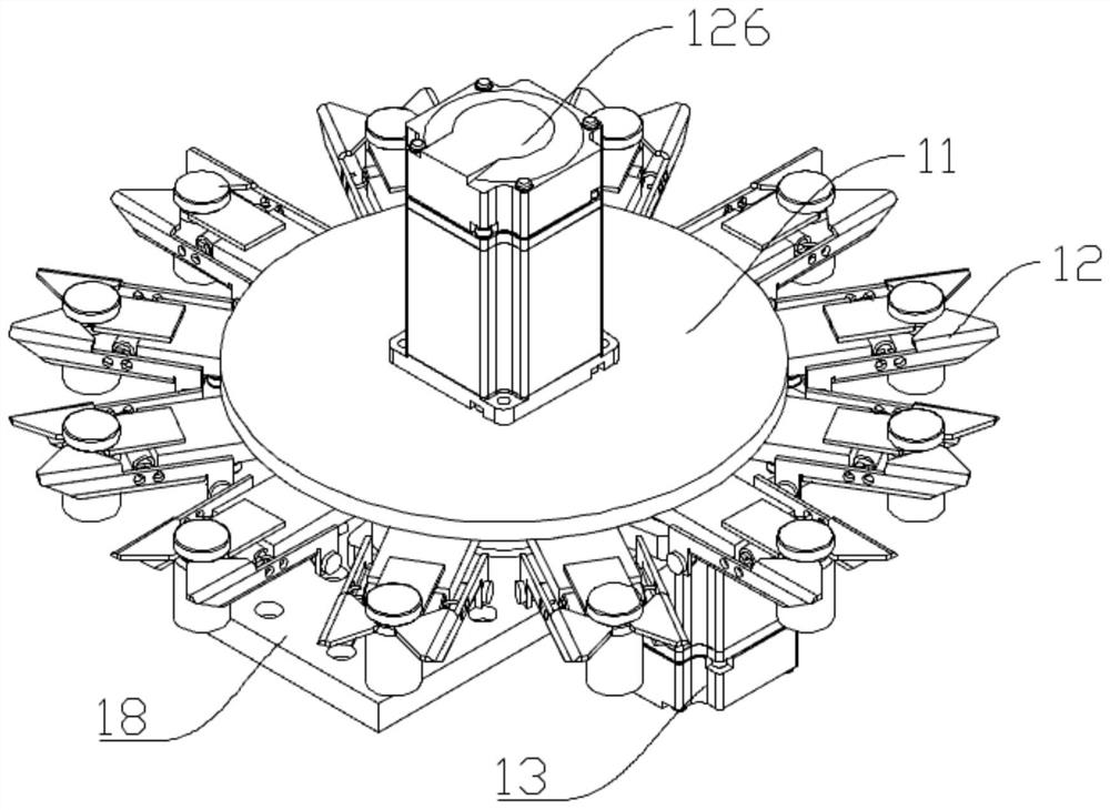
The invention relates to automatic clamping equipment and an automatic part clamping system, and the automatic clamping equipment comprises a loading and unloading structure which is suitable for loading and unloading a to-be-clamped part; a conveying component which is suitable for conveying the to-be-clamped part to a clamping part facing the loading and unloading structure; and a pushing structure which is suitable for pushing the to-be-clamped part conveyed to the clamping part to the loading and unloading structure so as to clamp the to-be-clamped part. The automatic clamping equipment can automatically complete the operation of loading and unloading the to-be-clamped part, can overcome the defects of high repeatability, high labor intensity of an operator and danger in the process of limiting the part in the prior art, can improve the automation degree of the part assembly process, reduces the labor intensity of the operator, and dangerousness caused by manual limiting of the part is avoided.

Description

technical field [0001] The invention relates to the technical field of component handling systems, in particular to an automatic clamping device and an automatic component clamping system. Background technique [0002] At present, when disassembling or repairing parts, the parts are generally limited manually. For example, when dispensing injection bottles, it is generally necessary to manually hold the injection bottle, and then hold the syringe out of the infusion bag. Inhale the liquid medicine, inject the liquid medicine into the injection bottle and suck it repeatedly, and then inject the liquid medicine into the infusion bag. Using this method to limit the position of parts not only has high repeatability, but also requires a lot of labor for the operator, and also has certain dangers. The process of liquid injection and liquid absorption is likely to cause injury to the operator. Contents of the invention [0003] Therefore, the technical problem to be solved by th...

Claims


Application Information

Patent Timeline
IPC IPC(8): B65B43/42B65B43/60B65B43/48B67C3/24B65G47/82B65G47/06
CPCB65B43/42B65B43/60B65B43/48B67C3/24B65G47/82B65G47/06B65G2201/0244B65G2201/0252Y02P70/50
Inventor 张天翼刘超王健谭畅
Owner ZHUHAI GREE INTELLIGENT EQUIP CO LTD
Learn More