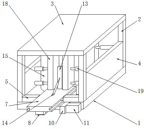
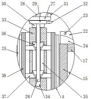
A gas cylinder stamping integrated molding equipment

A technology for forming equipment and gas cylinders, which can be applied to household appliances, hollow objects, other household appliances, etc., can solve the problems of danger, low quality, deformation, etc., and achieve the goal of improving stamping forming efficiency, reasonable and reliable structure, and improving work efficiency. Effect

Active Publication Date: 2022-03-25
南通上成金属科技有限公司
View PDF10 Cites 0 Cited by
  • Summary
  • Abstract
  • Description
  • Claims
  • Application Information

AI Technical Summary

Problems solved by technology

[0003] In the patent document "CN206483866U A Gas Cylinder Preform Stamping Device", it cools the entire punch, the cooling effect is uniform, and the punch is continuously cooled, and the cooling efficiency is high, but it lacks the integral molding function, usually the gas cylinder is integrated Especially for the stamping of nitrogen dioxide gas cylinders, the bottle body is difficult to achieve integrated molding, and the quality after molding is low, prone to local deformation and other problems, affecting the service life of the gas cylinders, and also causing danger. Moreover, the nitrogen dioxide gas cylinder is inconvenient to close, and it is difficult to realize rapid prototyping before cooling, which affects the production efficiency of the gas cylinder. After the molding is completed, it is difficult to realize the rapid removal of the gas cylinder, which brings difficulties to the transportation of the gas cylinder and affects the production of the gas cylinder efficiency
At present, there is no gas cylinder stamping integrated molding equipment with reasonable and reliable structure, integrated molding function and guaranteed molding quality.

Method used


Image

  • A gas cylinder stamping integrated molding equipment
  • A gas cylinder stamping integrated molding equipment
  • A gas cylinder stamping integrated molding equipment

Examples


Embodiment Construction

[0031]In order to enable those skilled in the art to better understand the solution of the present application, the technical solution in the embodiment of the application will be clearly and completely described below in conjunction with the accompanying drawings in the embodiment of the application. Obviously, the described embodiment is only It is an embodiment of a part of the application, but not all of the embodiments. Based on the embodiments in this application, all other embodiments obtained by persons of ordinary skill in the art without creative efforts shall fall within the scope of protection of this application.

[0032] It should be noted that the terms "first" and "second" in the description and claims of the present application and the above drawings are used to distinguish similar objects, but not necessarily used to describe a specific sequence or sequence. It should be understood that the data so used may be interchanged under appropriate circumstances for ...


PUM


Abstract

This application belongs to the field of gas cylinder application technology, and discloses a gas cylinder stamping integrated forming equipment, which includes: a bottom plate, a support rod, a top plate, a side plate, a guide plate, a guide block, a conveying plate, a rack, a guide groove, and a fixing seat , conveying motor, conveying gear, splint, electric push rod, mold base, gap, support plate, side plate, first hydraulic cylinder, fixed plate, second hydraulic cylinder, closing mold, guide rod, opening, cylinder blank, The third hydraulic cylinder, mounting plate, fixed rod, gear plate, inserting plate, adjusting motor, adjusting gear, movable plate, slot, chute, wedge block, connecting rod, side pressure plate, stamping die and inserting groove. This application adopts the splicing mold base for the stamping and forming of the gas cylinder, realizes the rapid stamping and forming of the bottle bottom and the bottle body, improves the stamping and forming efficiency, and also has the closing function to ensure the integrated forming effect of the gas cylinder, and realizes the gas cylinder through the opening of the mold The rapid transportation improves the working efficiency of the gas cylinder stamping integrated molding equipment.

Description

technical field [0001] The invention relates to a gas cylinder stamping integrated molding equipment, in particular to a gas cylinder stamping integrated molding equipment, which belongs to the technical field of gas cylinder applications. Background technique [0002] A gas cylinder refers to a mobile pressure container that can be re-inflated under normal circumstances to hold permanent gas, liquefied gas or dissolved gas. , Explosive, toxic, strong corrosion and other properties, according to the manufacturing method can be divided into welded gas cylinders, controlled gas cylinders, drawn drawn gas cylinders and wound gas cylinders, the generalized gas cylinders should include different pressures, different volumes, Disposable or refillable mobile pressure vessels with different structural forms and different materials for storage and transportation of permanent gas, liquefied gas and dissolved gas. From the structural classification, there are seamless gas cylinders and...

Claims


Application Information

Patent Timeline
Patent Type & Authority Patents(China)
IPC IPC(8): B21D51/24
CPCB21D51/24
Inventor 高锋
Owner 南通上成金属科技有限公司
Why Eureka
Try Eureka