
Satellite communication load based on microwave photons

A microwave photonic and satellite communication technology, applied in the satellite communication system and the microwave photonics field, can solve the problems of not being able to give full play to the advantages of microwave photonic technology, unable to meet the switching and forwarding requirements of sub-channels within beams and between beams, etc., achieving light weight and volume. Small, instantaneous bandwidth effects

Inactive Publication Date: 2022-02-08
军事科学院系统工程研究院网络信息研究所
View PDF2 Cites 0 Cited by
  • Summary
  • Abstract
  • Description
  • Claims
  • Application Information

AI Technical Summary

Problems solved by technology

[0004] In Chinese patent CN110365401A, a communication satellite forwarding device and its forwarding method based on microwave photonics are disclosed. Microwave photonics technology is used to realize low-loss, large-bandwidth on-satellite bent-pipe forwarding, but this method can only realize microwave beam Large-grained switching between beams cannot meet the switching and forwarding requirements of intra-beam and inter-beam sub-channels
Chinese patent CN110601769B discloses a space-borne array microwave frequency conversion switching system based on microwave photons and its implementation method. Through the two-level switching of the optical domain and the electrical domain, fine-grained on-board switching is realized, but the switching is carried out in the electrical domain. Digital processing is still limited by electronic bottlenecks and cannot fully exploit the advantages of microwave photonics technology

Method used


Image

  • Satellite communication load based on microwave photons
  • Satellite communication load based on microwave photons
  • Satellite communication load based on microwave photons

Examples


Embodiment Construction

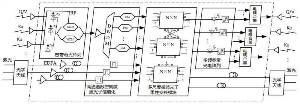
[0023] Such as figure 1 As shown, the invention discloses a satellite communication load based on microwave photons, which includes a transceiver antenna unit and an optical domain signal processing and switching unit.

[0024] The transceiver antenna unit includes a multi-band microwave antenna and an optical antenna array. The multi-band microwave antenna supports the reception and transmission of Q / V, Ka and Ku band microwave signals, and the optical antenna array supports the reception and transmission of multiple laser signals.

[0025] The optical domain signal processing switching unit includes a broadband electro-optical array, a high-channel-number dense microwave photonic channelization module, a multi-scale microwave photonic flexible switching module and a multi-frequency broadband photoelectric array, and the broadband electro-optical array is connected with a high-channel-number dense microwave photonic channelization module , the high channel number dense microw...


PUM


Abstract

The invention discloses a satellite communication load based on microwave photons, which comprises a receiving and transmitting antenna unit and an optical domain signal processing and switching unit, the receiving and transmitting antenna unit comprises a multi-band microwave antenna and an optical antenna array, and the optical antenna array supports receiving and transmitting of multiple paths of laser signals. The optical domain signal processing switching unit comprises a broadband electro-optical array, a high-channel-number dense microwave photon channelization module, a multi-scale microwave photon flexible switching module and a multi-frequency broadband electro-optical array. The broadband electro-optical array is used for completing integrated low-stray and high-linearity electro-optical modulation of multiple paths of microwave signals with different frequency bands. The channelization module realizes variable bandwidth optical domain sub-channel division, and the flexible switching module completes variable granularity switching of multiple paths of optical signals. The satellite communication microwave photon load framework has the advantages of being wide in working frequency band, large in instantaneous bandwidth, free of electromagnetic interference, flexible in access, small in size, light in weight and the like, and the satellite communication microwave photon load framework with multi-frequency-band integration, low loss, large bandwidth and multi-scale flexible exchange can be achieved.

Description

technical field [0001] The invention relates to the technical fields of satellite communication systems and microwave photons, in particular to a satellite communication payload based on microwave photons. Background technique [0002] As an important part of the communication system, satellite communication has the advantages of wide coverage, communication frequency bandwidth and no geographical constraints. It can realize large-area communication networking and flexible global coverage. It is an indispensable and important part of the communication field. . With the rapid development of information technology and aerospace technology, future satellite communications are constantly developing in the direction of large bandwidth, multi-granularity transmission, and high-speed space networking, which puts forward higher requirements for on-board transmission capabilities and networking switching capabilities. Traditional satellite communication systems usually use microwave...

Claims


Application Information

Patent Timeline
IPC IPC(8): H04B10/516H04B10/70
CPCH04B10/516H04B10/70Y02D30/70
Inventor 何元智刘韵
Owner 军事科学院系统工程研究院网络信息研究所
Learn More