
Engineering machinery cab surface treatment method

A technology for surface treatment and construction machinery, applied in the field of surface treatment of construction machinery cabs, can solve the problems of inability to ensure the safety of construction workers, poor ventilation and ventilation in the cab, and increased cab testing, so as to avoid direct impact extrusion. , easy to turn on and off, high-security effects

Pending Publication Date: 2022-02-08
安徽福本机械制造有限公司
View PDF8 Cites 0 Cited by
  • Summary
  • Abstract
  • Description
  • Claims
  • Application Information

AI Technical Summary

Problems solved by technology

[0005] The technical problems solved by the present invention are: during the construction of construction machinery, external environmental factors will increase the test of the driver's cab, which cannot ensure the safety of construction personnel; the ventilation effect in the driver's cab is poor

Method used


Image

  • Engineering machinery cab surface treatment method
  • Engineering machinery cab surface treatment method
  • Engineering machinery cab surface treatment method

Examples


Embodiment 1

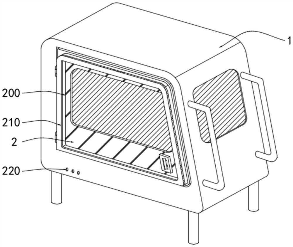
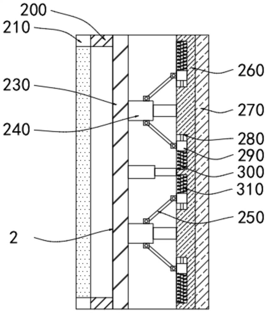
[0034] Both sides of the driver’s cab 1 are rotatably connected to the door 2 through pin shafts. The edge of the outer surface of the door 2 is fixedly connected with a protective ring 200. The surface of the protective ring 200 is matched with a backing plate 210. The door 2 consists of a steel plate. 260, one side of the steel plate 260 is pressed with an outer guard plate 230, and the other side of the steel plate 260 is provided with an inner protective PVC insulating plate 270, which adopts three layers of protection of the outer guard plate 230, the steel plate 260 and the inner protective PVC insulating plate 270 , can reduce the impact of factors of the external engineering environment on the warehouse door 2 .

[0035] The inside of the outer guard plate 230 and the steel plate 260 is provided with an anti-seismic buffer protection mechanism. The anti-seismic buffer protection mechanism includes a telescopic sleeve rod 240 arranged at the joint between the outer guard...

Embodiment 2

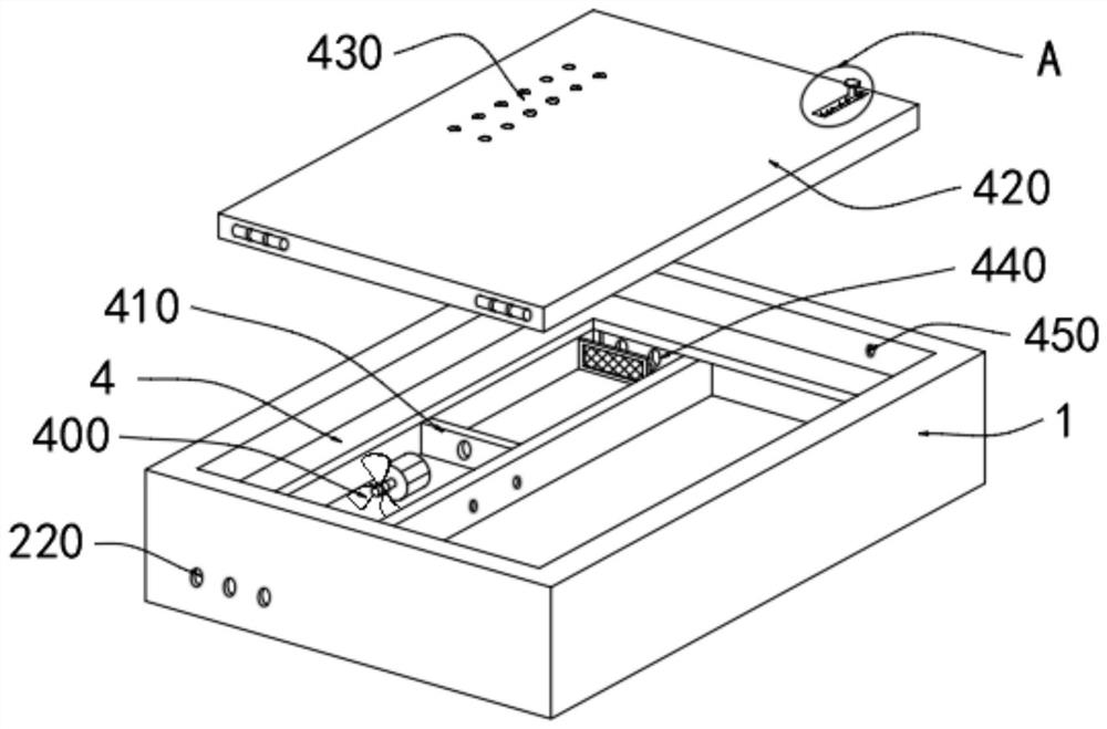
[0039] The bottom surface of the inner cavity of the driver's cab 1 is provided with a storage clean air chamber 4, which can place some equipment used in construction machinery. The blower fan 400 fixed at the bottom of the clean air chamber 4, one side of the blower fan 400 is provided with an air hole plate 410, the side surface of the storage clean air chamber 4 is provided with an exhaust hole 220, and the storage clean air chamber 4 The other side surface is provided with an outer air inlet 440, and the outer air inlet 440 is on the same straight line as the exhaust hole 220, and the top of the wall plate is provided with a sealing plate 420 connected with the storage clean air chamber 4 through a hinge, and the sealing The bottom surface of the plate 420 is provided with a clamp seat 460 matching the wall plate, the bottom surface of the clamp seat 460 is provided with a cavity 470, and the top surface of the sealing plate 420 is provided with an inner cavity 470 matchin...


PUM


Abstract

The invention discloses an engineering machinery cab surface treatment method, and particularly relates to the technical field of engineering machinery cables.The engineering machinery cab surface treatment method comprises the specific operation steps that firstly, a protective ring and a base plate are additionally arranged at the edge position of the outer surface of a bin door, and collision occurring after the bin door is opened is reduced; and secondly, an anti-seismic buffering protection mechanism is arranged in the bin door. One part of external force borne by the device directly acts on the steel plate through the telescopic sleeve rod, the other part of external force transmits the borne pushing external force to the connecting rod through the outer wall of the fixed end of the telescopic sleeve rod, the sliding base is pushed to slide on the sliding rod, the sliding base extrudes the pressure spring, and the other part of external force borne by the outer protection plate is reduced to the steel plate; direct impact and extrusion of external force on the steel plate are avoided, overlarge deformation of the bin door is avoided, the personal safety of constructors in the cab is protected, the cab is higher in design safety performance, air in the cab is extracted through the draught fan, and a clean driving environment can be provided for the cab.

Description

technical field [0001] The invention relates to the technical field of construction machinery cabs, in particular to a surface treatment method for construction machinery cabs. Background technique [0002] With the acceleration of industrialization, construction machinery has been widely used in all aspects of social construction. The cab of construction machinery is the working area for operating mechanical equipment. Construction machinery such as hydraulic excavators usually have a host and can perform the actions required for engineering operations. A working device and a cab mounted on the main machine are equipped with a driver's seat on which an operator sits and a control box including an operating lever. [0003] The safety performance of the current construction machinery cab has been greatly tested. When the external environment of the project is complex and diverse, it may endanger the personal safety of the construction personnel in the cab. In addition, during...

Claims


Application Information

Patent Timeline
IPC IPC(8): B62D33/06B60H1/00B60H3/00E02F9/16
CPCB62D33/06B60H1/00357B60H1/00457B60H3/00E02F9/163
Inventor 刘文国吕立贤胡松王威王如
Owner 安徽福本机械制造有限公司
Learn More