


Quick Research
Generate reliable direction feasibility study reports for your R&D in just a few steps.

Technical Q&A
Discover and master advanced knowledge NOW. Basics, ideas, possibilities, all at once.

Find Solutions
As an expert in R&D theories, this can generate solutions to your technical problems instantly.

Evaluate Feasibility
Analyze your overall solution with one click, know your potential R&D risks in advance.

Monitor Landscape
Get weekly tech updates, stay abreast of the latest tech innovations and key insights.
Ventilation system
A technology of ventilation system and ventilation hole, which is applied in the field of ventilation system and can solve problems such as the inability to effectively use underground space
- Summary
- Abstract
- Description
- Claims
- Application Information
AI Technical Summary
Problems solved by technology
Method used
Image

Examples
no. 1 Embodiment approach
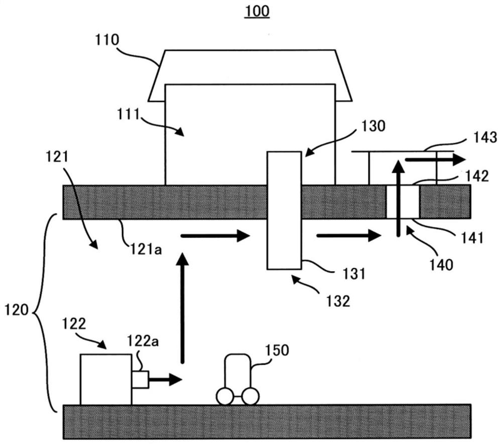
[0022] The ventilation system 100 of the first embodiment will be described. figure 1 It is a schematic diagram of the ventilation system 100.
[0023] like figure 1 In that case, the ventilation system 100 includes a building 110, which has space 111 inside; underground apparatus 120, which is disposed underground, and has underground space 121 inside; communication passage 130, which makes space 111 and The underground space 121 communicates; and the vent hole 140 that connects the upper ground and underground space 121 of the building 110.
[0024] The use of buildings 110 is not particularly limited, and can be a house or a office. The building 110 has space 111 internally. Preferred space 111 is a living space that people can live. Further, in the case where the building 110 has a basement, the underground device 120 can also be disposed at a position that is more underground than the basement.
[0025] Underground device 120 has underground space 121 internally. The use of t...
no. 2 Embodiment approach
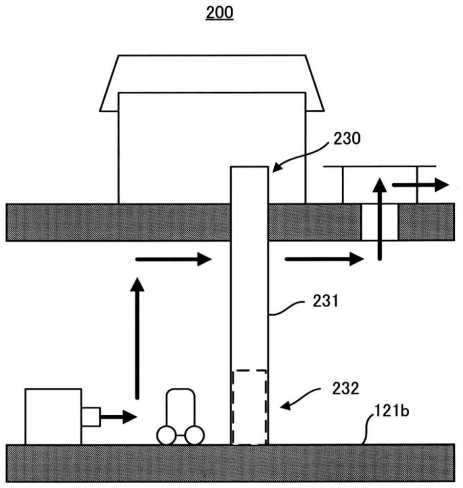
[0037] The ventilation system 200 of the second embodiment will be described. figure 2 A schematic diagram showing the ventilation system 200. The venting system 100 and the vent system 200 differ in the lifting machine which is subjected to the inside of the communication passage 230, which is the same as those other than the structure. Therefore, hereinafter, it is intended to be in connection with the communication passage 230.
[0038] For communication 230, the side wall 231 extends from the ceiling 121a to the ground 121b of the underground space 121, and there is an elevator that can be used to move the article up and down in the inner passage 230.
[0039] Further, the communication passage 230 removes a portion of the side wall 231 on the side 121b side, including: a first opening portion 232 that is opened at a vertical direction formed by the side wall 231 and the ground 121b ( figure 2 Denal line portion). The first opening portion 232 has a door (not shown) capable of...
no. 3 Embodiment approach
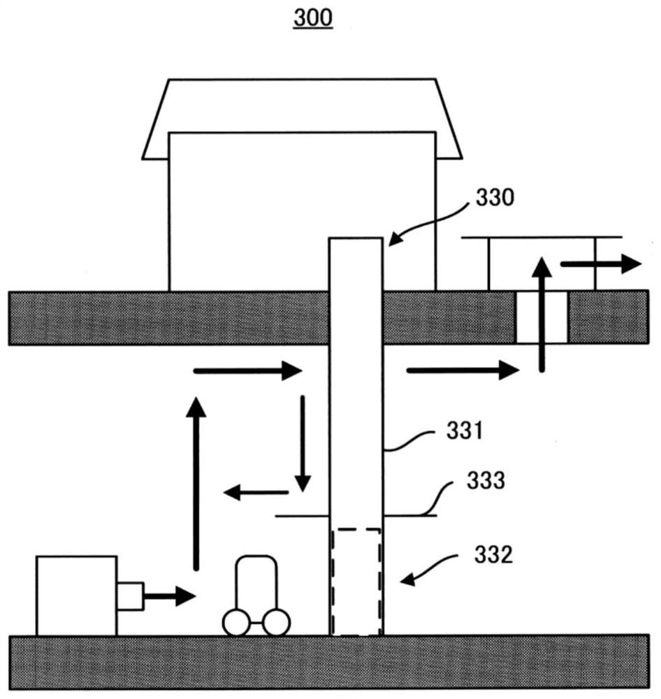
[0042] The ventilation system 300 of the third embodiment will be described. image 3 A schematic diagram showing the ventilation system 300. The different point of the ventilation system 200 and the vent system 300 is to provide the eave portion 333 in the communication passage 330, except that the structure is the same. Therefore, the following is focused on the communication 330.
[0043] The sidewall 331 of the communication path 330 has an eave portion 333 that protrudes from the side wall 331 toward the outer side of the communication passage 330. Further, the orientation portion 333 is disposed on the upper side of the first opening portion 332 on the side of the underground space 121 of the communication passage 330, and the secondary passage 330 is disposed on the second of the exhaust port 122a to the vent hole 140 from the fuel cell unit 122. When the opening portion 141 is connected, the sidewall 333 is disposed on the side wall 331 on the side of the exhaust port 122a,...
PUM
 Abstract
Description
Claims
Application Information
 - R&D Engineer
- R&D Manager
- IP Professional
- Industry Leading Data Capabilities
- Powerful AI technology
- Patent DNA Extraction
Browse by: Latest US Patents, China's latest patents, Technical Efficacy Thesaurus, Application Domain, Technology Topic, Popular Technical Reports.
© 2024 PatSnap. All rights reserved.Legal|Privacy policy|Modern Slavery Act Transparency Statement|Sitemap|About US| Contact US: help@patsnap.com