Closed centrifugal device

A centrifugal device and closed technology, which is applied in the direction of analytical material containers, laboratory utensils, laboratory containers, etc., can solve the problems of complicated operation process and contamination, so as to simplify the structure of the device, avoid contact and reduce pollution The effect of the risk

Pending Publication Date: 2022-02-01
苏州戴氏电子信息科技有限公司
View PDF2 Cites 0 Cited by
  • Summary
  • Abstract
  • Description
  • Claims
  • Application Information

AI Technical Summary

Problems solved by technology

[0008] The existing patent CN201721562489.7 provides an improved sampling device, through the action of air pressure to ensure the sterile state of the bioreactor and sampling device in the process of multiple sampling or continuous sampling, and at the same time improve the efficiency of sampling during the biological reaction test ; but in the process of aseptic sampling, it is necessary to pressurize the bioreactor first, and then pressurize from the position of the second tube, and the operation process is relatively complicated; in addition, the whole device includes a centrifuge tube, a first tube and a second tube. The sealing cap of the centrifuge tube is provided with a first hole and a second hole, which is not an integrated tube structure, and there is still a risk of contamination for the liquid in the tube
[0009] Another patent CN201721017811.8 provides a sterile centrifuge tube set capable of keeping the centrifuge tube sterile, including an outer tube and an inner tube as a whole; the whole invention aims to keep the inner tube sterile and airtight before and after centrifugation , which is conducive to various aseptic operations after centrifugation; however, the inner tube includes the tube body, inner tube plug, sealing cap and inner tube accessories, and is not an integrated tube body structure; when actually injecting samples, it is necessary to open / cover the seal Cap and inner tube plug, there is a risk of contamination for the liquid in the tube
[0010] The present invention is aimed at the application limitations of the above-mentioned prior art, and proposes a new type of closed centrifuge that can be used in conjunction with the existing centrifuge and achieve the centrifugation effect of cell enrichment in a closed state

Method used


Image

  • Closed centrifugal device
  • Closed centrifugal device
  • Closed centrifugal device

Examples


Embodiment 1

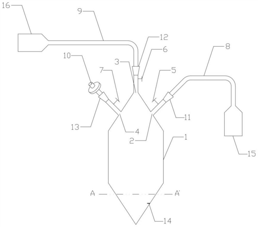
[0075] The overall structure of the closed centrifugal device with three openings of the present invention, such as figure 1 and Figure 4 and Figure 6 shown.

[0076] The device includes a pipe body (1), a liquid inlet (2), a liquid outlet (3), a vent (4), a valve a (5), a valve b (6), a valve c (7), a liquid inlet pipeline (8), outlet pipeline (9), air filter element (10), luer connector a (11), luer connector b (12), luer connector c (13), enclosure (14), Sample container (15), collection container (16), protective cap a (17), protective cap b (18), protective cap c (19), protective cover (20);

[0077] The upper and lower parts of the pipe body (1) are in the shape of a cone, and the middle part is in the shape of a cylinder;

[0078] The liquid inlet (2), the liquid outlet (3) and the vent (4) are all arranged on the cone on the same side of the pipe body (1), and the liquid outlet (3) is arranged on the cone the tip of the upper part;

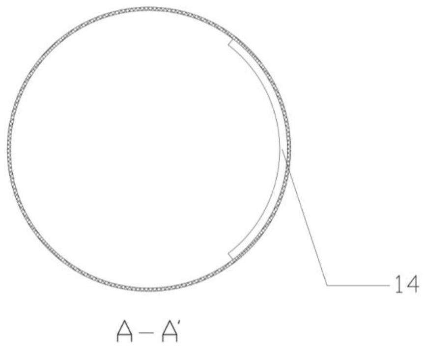
[0079] A fence (14) is arra...

Embodiment 2

[0098] Utilize the closed centrifugal device of the present invention to carry out centrifugal operation

[0099] Centrifugal enrichment was tested with Jurkat cells.

[0100] The RPMI 1640 culture medium that has added 10% (v / v) fetal calf serum is carried out cell culture, culture density 0.2-3 * 10 6 / mL. Before the test, cell count and viability detection were performed, and the viability detection was analyzed by APC-AnnexinⅤ / 7AAD staining and flow cytometry. The total cell density was 2.32 × 10 6 / mL, the ratio of AnnexinⅤ- / 7AAD- living cells was 96.5%.

[0101] Utilize the present invention figure 1 Collect 150 mL of cell culture in the shown centrifuge tube (hereinafter referred to as centrifuge tube 1) and common uncapped centrifuge tube (hereinafter referred to as centrifuge tube 2), and centrifuge at 200 g, 250 g, and 300 g for 3 min and 5 min, respectively. After the centrifugation, the centrifuge tube was inverted to discard the supernatant, and then the cell...

Embodiment 3

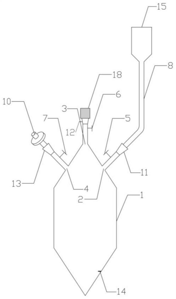
[0106] The overall structure of the tubular body of the closed centrifugal device with four openings of the present invention, such as Figure 7 and Figure 8 shown.

[0107] The device comprises a pipe body (1), a liquid inlet (2), a liquid outlet (3), a vent (4), a fourth opening (28), a liquid inlet line (8), and a liquid outlet line (9), air filter (10), sample container (15), suction tube (27), suction line (30), collection container (16), negative pressure collection device (29), needleless connector a ( 23), needleless connector b(24), needleless connector c(25), needleless connector d(26), protective cap a(17), protective cap b(18), protective cap c(19), protective cap d (31), protective cover (20).

[0108] The liquid inlet (2), the liquid outlet (3), the vent (4), and the fourth opening (28) are all arranged on the same side cone on the top of the pipe body (1), and the liquid outlet (3) set on the tip of the cone;

[0109] The liquid inlet (2), the liquid outle...


PUM


Abstract

The invention relates to a closed centrifugal device which comprises a pipe body, wherein the pipe body is provided with at least three openings, namely a liquid inlet, a liquid outlet and an air vent. The closed centrifugal device provided by the invention can perform centrifugal operation on a cell suspension in a closed state, realizes rapid liquid feeding / liquid discharging / liquid changing of liquid, greatly reduces the risk that a biological sample is polluted, and meets the requirement that treatment of three types of medical instrument samples required by laws and regulations must be totally closed at the same time.

Description

technical field [0001] The invention relates to a closed centrifugal device, more specifically, the invention relates to a device for separating cells and cell culture fluid in a closed state. Background technique [0002] Centrifuge tubes are defined as tubular liquid containers that can be used for centrifugation, and have been widely used in biological sciences, especially in the fields of biochemistry and molecular biology research. Centrifugal technology is mainly used for the separation and preparation of various biological samples. The suspension of biological samples is placed in a centrifuge tube. Under high-speed rotation, due to the huge centrifugal force, the suspended tiny particles (such as cells, biological macromolecules, etc.) It settles at a certain speed and accumulates at the bottom of the centrifuge tube, thereby being separated from the solution. Centrifuge tubes are an essential structural component of centrifugation technology, and centrifuge tubes o...

Claims


Application Information

Patent Timeline
IPC IPC(8): B01L3/14
CPCB01L3/00B01L3/5021B01L2300/048B01L3/50B01D17/0217B01D21/262B01L2200/0684B01L2400/0409B04B5/0414B04B2005/0478
Inventor 戴晓兵
Owner 苏州戴氏电子信息科技有限公司
Why Eureka
Try Eureka