
Intelligent reflector beam forming and phase shift design method based on alternating directions

A beamforming, alternate direction technology, applied in the field of intelligent reflector beamforming and phase shift design, can solve problems such as high complexity and performance loss, achieve low complexity, good bit error rate performance, and maximize the overall The effect of the received signal-to-noise ratio

Active Publication Date: 2022-01-28
UNIV OF ELECTRONIC SCI & TECH OF CHINA
View PDF4 Cites 0 Cited by
  • Summary
  • Abstract
  • Description
  • Claims
  • Application Information

AI Technical Summary

Problems solved by technology

[0004] On the other hand, in order to solve the non-convex problem of joint optimization of beamforming and phase shift design in MIMO systems, conventional RIS technology solutions often result in performance loss and high complexity

Method used


Image

  • Intelligent reflector beam forming and phase shift design method based on alternating directions
  • Intelligent reflector beam forming and phase shift design method based on alternating directions
  • Intelligent reflector beam forming and phase shift design method based on alternating directions

Examples


Embodiment Construction

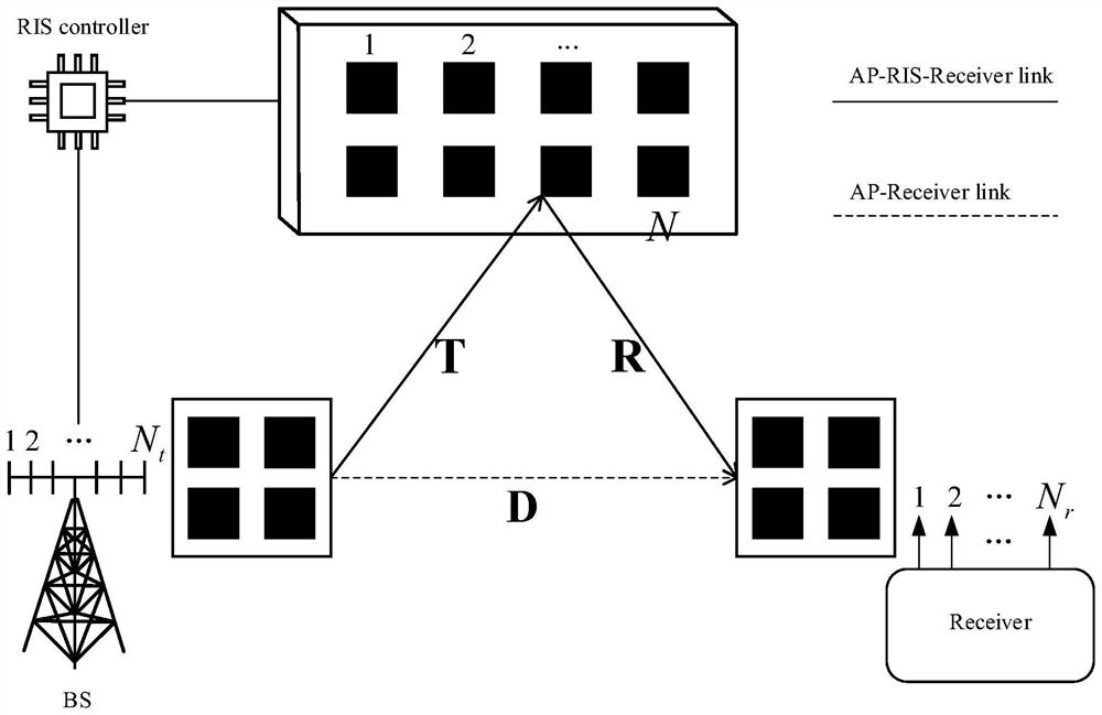
[0028] The specific implementation manners of the present invention will be further described in detail below in conjunction with the accompanying drawings.

[0029] The optimization of the beamforming vector is first performed with a fixed phase shift. For a fixed Θ, the optimization problem can be converted to:

[0030]

[0031] s.t.||w|| 2 ≠0,

[0032] because and H H H=(H H h) H , the objective function can be transformed into:

[0033]

[0034] in,(·) H Represents the conjugate transpose operation of a matrix, λ max (H H H) means H H The largest eigenvalue of H. when||w|| 2 = 1 to obtain the maximum eigenvalue.

[0035] According to the above derivation, the optimal beamforming vector is corresponding to H H The eigenvector of the largest eigenvalue of H, that is

[0036]

[0037] in

[0038] [V,Λ]=eig(H H h)

[0039] eig is the matrix eigenvalue decomposition function, is the index of the largest eigenvalue in Λ, w opt is the optimal beam...


PUM


Abstract

The invention belongs to the technical field of wireless communication, and particularly relates to an intelligent reflector beam forming and phase shift design method based on alternating directions. According to the scheme, the non-convex problem of initial wave beam forming and phase shift design joint optimization is mainly resolved into the following two processes: 1) wave beam forming vectors are optimized under a fixed phase shift condition, and 2) when other phase shifts and wave beam forming vectors are fixed, a specific phase shift is determined, and a closed solution of the specific phase shift is deduced. Through simulation verification, the intelligent reflector beam forming and phase shift design scheme based on the alternating direction has relatively low complexity and relatively good bit error rate performance.

Description

technical field [0001] The invention belongs to the technical field of wireless communication, and in particular relates to an intelligent reflective surface beam forming and phase shifting design method based on alternating directions. Background technique [0002] In recent years, smart reflector technology has been widely discussed as a potential candidate for future 6G networks, with the advantages of improving signal quality, energy efficiency, and throughput. The unique ability to manipulate the phase shift of reflected signals through its low-cost components makes smart reflective surfaces an excellent wireless communication technology. [0003] Current research shows that RIS (Reconfigurable Intelligent Surface) components can adjust the phase shift of reflected electromagnetic waves by changing the reflection coefficient through the controller to provide considerable multipath diversity gain without expensive hardware requirements. [0004] On the other hand, in or...

Claims


Application Information

Patent Timeline
IPC IPC(8): H04B7/0413H04B7/06G06F30/20
CPCH04B7/0413H04B7/0617G06F30/20Y02D30/70H04B7/04013
Inventor 牛鸿蒋伟雷霞
Owner UNIV OF ELECTRONIC SCI & TECH OF CHINA
Learn More