


Quick Research
Generate reliable direction feasibility study reports for your R&D in just a few steps.

Technical Q&A
Discover and master advanced knowledge NOW. Basics, ideas, possibilities, all at once.

Find Solutions
As an expert in R&D theories, this can generate solutions to your technical problems instantly.

Evaluate Feasibility
Analyze your overall solution with one click, know your potential R&D risks in advance.

Monitor Landscape
Get weekly tech updates, stay abreast of the latest tech innovations and key insights.
Novel test fixture and test method suitable for microwave assembly
A technology of microwave components and test fixtures, which is applied in the field of measurement and testing, can solve problems such as poor reliability and slow microwave component testing, and achieve the effect of improving test efficiency
- Summary
- Abstract
- Description
- Claims
- Application Information
AI Technical Summary
Problems solved by technology
Method used
Image


Examples
Embodiment 1
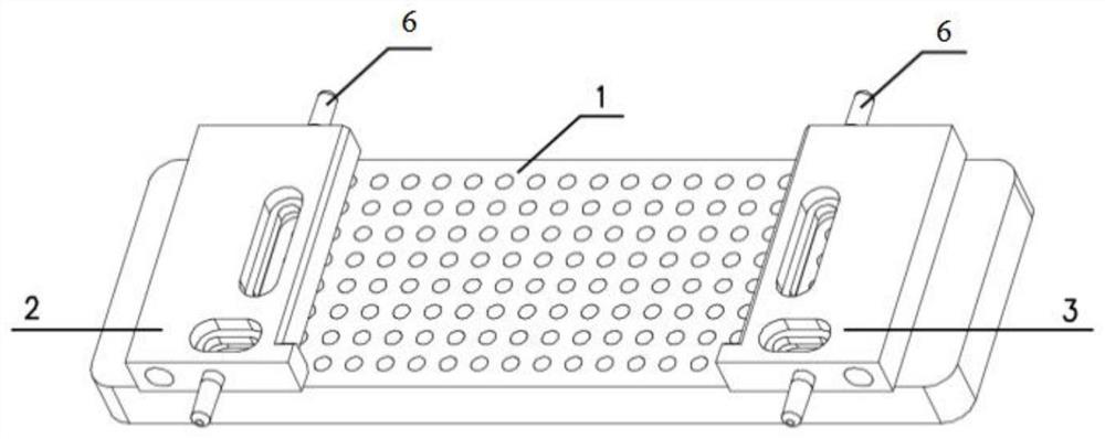
[0064] Such as Figure 1-3 As shown, a new type of test fixture suitable for microwave components, including a test base 1 and a detachable left fixed frame 2 assembled on the test base 1, a right fixed frame 3, a type A combination fixture 4, and a B type combination Fixture 5, the fastening positions of the left side fixing frame 2 and the right side fixing frame 3 on the test base 1 are adjustable;
[0065] The test base 1, the left fixing frame 2, the right fixing frame 3, the A-type combination fixture 4 and the B-type combination fixture 5 are used to fix the microwave component, the test base 1 is located at the bottom of the microwave component, the left side fixing frame 2, the right side The fixed frame 3, the A-type combined fixture 4 and the B-type combined fixture 5 are located around the microwave assembly;
[0066] Such as Figure 4 As shown, the A-type combination fixture 4 includes a detachable A-type combination fixture frame 41 assembled on the upper ends ...
Embodiment 2
[0078] Such as Figure 7-8 As shown, a new test method suitable for microwave components includes the following steps:
[0079] S1, install the left fixed frame 2 and the right fixed frame 3 on the test base 1, install the B-type combined fixture 5 on the lower end of the left fixed frame 2 and the right fixed frame 3, put the microwave assembly, and place The radio frequency adapter 421 on the B-type combined fixture 5 is assembled with the radio frequency port of the microwave component, and then the A-type combined fixture 4 is fixed on the upper ends of the left fixed frame 2 and the right fixed frame 3;
[0080] S11. Assembling the test base: install the left fixed frame 2 and the right fixed frame 3 on the test base 1, adjust the positions of the left fixed frame 2 and the right fixed frame 3 so that the microwave components can be put in;
[0081] The left fixing frame 2, the right fixing frame 3 and the test base 1 are fixed in multiple positions so as to adjust the dis...
Embodiment 3
[0092] A novel test method applicable to microwave components, comprising the following steps:
[0093] (1) Install the radio frequency test cable assembly 42 on the A-type composite fixture frame 41 and fasten it with screws; install the video test cable assembly 43 on the A-type composite fixture frame 41 and fasten it with screws.
[0094] (2) Install all the radio frequency test cable assemblies 42 on the B-type combination fixture frame 51 and fasten them with screws.
[0095] (3) Connect the test cable assemblies on the A-type combination fixture 4 and the B-type combination fixture 5 with corresponding test equipment.
[0096] (4) Install the left fixed frame 2 and the right fixed frame 3 on the test base 1, adjust the positions of the left fixed frame 2 and the right fixed frame 3, and ensure that the left fixed frame 2 and the right fixed frame 3 are in line with the There are gaps between microwave components.
[0097] (5) Fix the B-type combination fixture 5 on th...
PUM
 Abstract
Description
Claims
Application Information
 - R&D Engineer
- R&D Manager
- IP Professional
- Industry Leading Data Capabilities
- Powerful AI technology
- Patent DNA Extraction
Browse by: Latest US Patents, China's latest patents, Technical Efficacy Thesaurus, Application Domain, Technology Topic, Popular Technical Reports.
© 2024 PatSnap. All rights reserved.Legal|Privacy policy|Modern Slavery Act Transparency Statement|Sitemap|About US| Contact US: help@patsnap.com