
Constant-temperature bin and water heater

A technology of constant temperature and hot water, applied in fluid heaters, fluid heater control, lighting and heating equipment, etc., can solve problems such as limited effects, affecting users' bathing comfort, and excessive water temperature fluctuations, so as to improve comfort , Excellent constant temperature effect, small fluctuation of outlet water temperature

Pending Publication Date: 2022-01-28
SUPERMAN ZHONGSHAN ELECTRIC APPLIANCES CO LTD
View PDF8 Cites 0 Cited by
  • Summary
  • Abstract
  • Description
  • Claims
  • Application Information

AI Technical Summary

Problems solved by technology

[0002] For gas water heaters currently on the market, if the water valve is turned off and then turned on again in a short period of time, the hot water retained in the constant temperature chamber itself has a relatively high temperature, and the water stored in the water pipe will be heated due to heat exchange. The residual heat of the device continues to be heated, and its water temperature is much higher than the temperature of the hot water in the constant temperature tank. Therefore, the effect of using the hot water in the constant temperature tank to compensate for the temperature of the high-temperature storage water is relatively limited, and the final outlet water temperature is the same as the set temperature. There is still a large temperature difference, and the water temperature fluctuates too much during the water stop and boiling process, which seriously affects the user's bathing comfort

Method used


Image

  • Constant-temperature bin and water heater
  • Constant-temperature bin and water heater
  • Constant-temperature bin and water heater

Examples


Embodiment Construction

[0026] Embodiments of the present invention are described in detail below, examples of which are shown in the drawings, wherein the same or similar reference numerals designate the same or similar elements or elements having the same or similar functions throughout. The embodiments described below by referring to the figures are exemplary only for explaining the present invention and should not be construed as limiting the present invention.

[0027] In the description of the present invention, it should be understood that when referring to orientation descriptions, such as terms "upper", "lower", "front", "rear", "left", "right", "vertical", "horizontal" ", "top", "bottom", "inner", "outer" and other indicated orientations or positional relationships are based on the orientations or positional relationships shown in the drawings, and are only for the convenience of describing the present invention and simplifying the description, rather than indicating Or imply that the devic...


PUM


Abstract

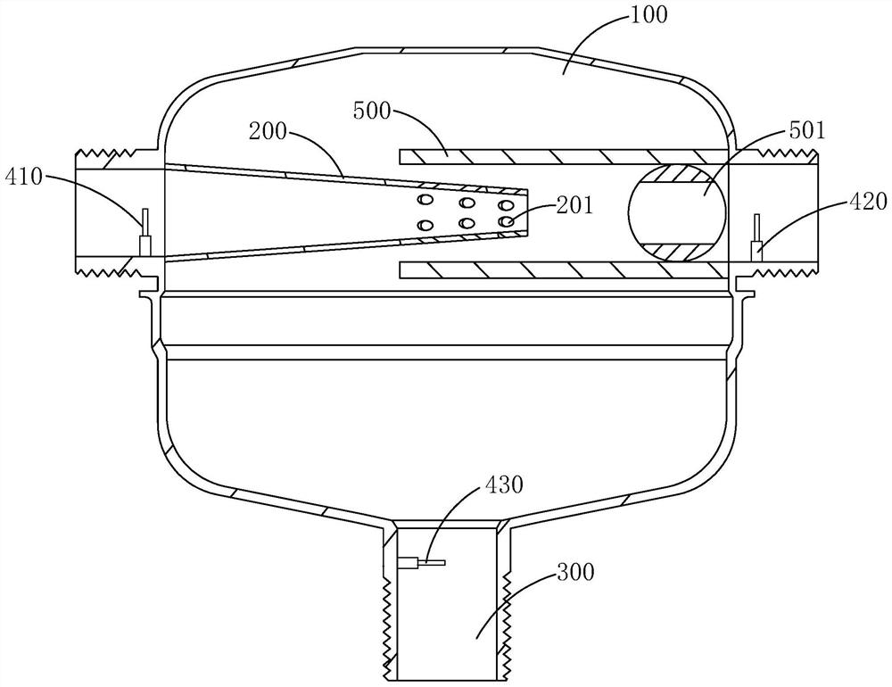
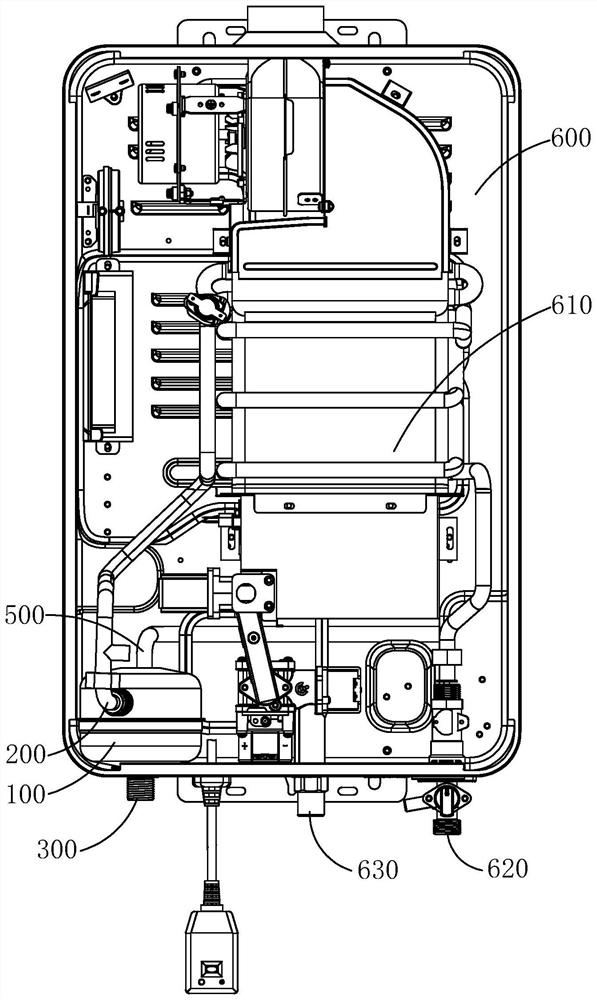
The invention discloses a constant-temperature bin and a water heater. The constant-temperature bin comprises a bin body, a first water temperature detection device, a cold water inlet pipe and a main control module, a hot water inlet pipe and a water outlet pipe are arranged on the bin body, and when the first water temperature detection device detects that high-temperature stored water enters a containing cavity of the bin body from the hot water inlet pipe, the main control module controls the operation of the cold water valve device to conduct the cold water inlet pipe, so that part of cold water is introduced into the containing cavity of the bin body to be mixed with the high-temperature stored water for cooling, and the mixed water flow can be further mixed with the hot water reserved in the containing cavity of the bin body. Therefore, cold water is introduced through the cold water inlet pipe to carry out water temperature compensation on the high-temperature stored water, the water temperature of the high-temperature stored water entering the bin body can be rapidly reduced, and the temperature difference between the water outlet temperature and the set temperature can be effectively reduced after the high-temperature stored water is mixed with the cold water and hot water reserved in the containing cavity and then discharged. Therefore, the water temperature fluctuation in the water cut-off and restarting process is reduced, and the comfort of a user for bathing with hot water is improved.

Description

technical field [0001] The invention relates to the technical field of water heaters, in particular to a constant temperature chamber and a water heater. Background technique [0002] For gas water heaters currently on the market, if the water valve is turned off and then turned on again in a short period of time, the hot water retained in the constant temperature chamber itself has a relatively high temperature, and the water stored in the water pipe will be heated due to heat exchange. The residual heat of the device continues to be heated, and its water temperature is much higher than the temperature of the hot water in the constant temperature tank. Therefore, the effect of using the hot water in the constant temperature tank to compensate for the temperature of the high-temperature storage water is relatively limited, and the final outlet water temperature is the same as the set temperature. There is still a large temperature difference, and the water temperature fluctu...

Claims


Application Information

Patent Timeline
Patent Type & Authority Applications(China)
IPC IPC(8): F24H9/00F24H9/20F24H15/176F24H15/215F24H15/219
CPCF24H9/0005F24H9/2035
Inventor 罗子健罗先明李发金
Owner SUPERMAN ZHONGSHAN ELECTRIC APPLIANCES CO LTD
Learn More