Thermally driven optical fibre switch for micromachinery and its making method

A technology of optical fiber switch and manufacturing method, which is applied in the coupling of optical waveguide and other directions, can solve the problems related to the alignment accuracy of optical fiber in switching performance and the relatively large relationship between the process complexity and the driving mode of micromirror, and achieve low cost, good reliability, The effect of low insertion loss

Inactive Publication Date: 2004-02-25
SOUTHEAST UNIV
View PDF0 Cites 3 Cited by
  • Summary
  • Abstract
  • Description
  • Claims
  • Application Information

AI Technical Summary

Problems solved by technology

Because the former does not need to move the optical fiber, it can realize N×M (N, M≥2) optical switch array, and the micromirror drive can be realized in various ways (for example: hinge type, sliding type, electrostatic drive type, electromagnetic drive type etc.), the disadvantage is that the complexity of the process is closely related to the driving method of the micromirror. The latter process is relatively simple, but the switching performance is related to the alignment accuracy of the optical fiber

Method used


Image

  • Thermally driven optical fibre switch for micromachinery and its making method
  • Thermally driven optical fibre switch for micromachinery and its making method

Examples


Embodiment Construction

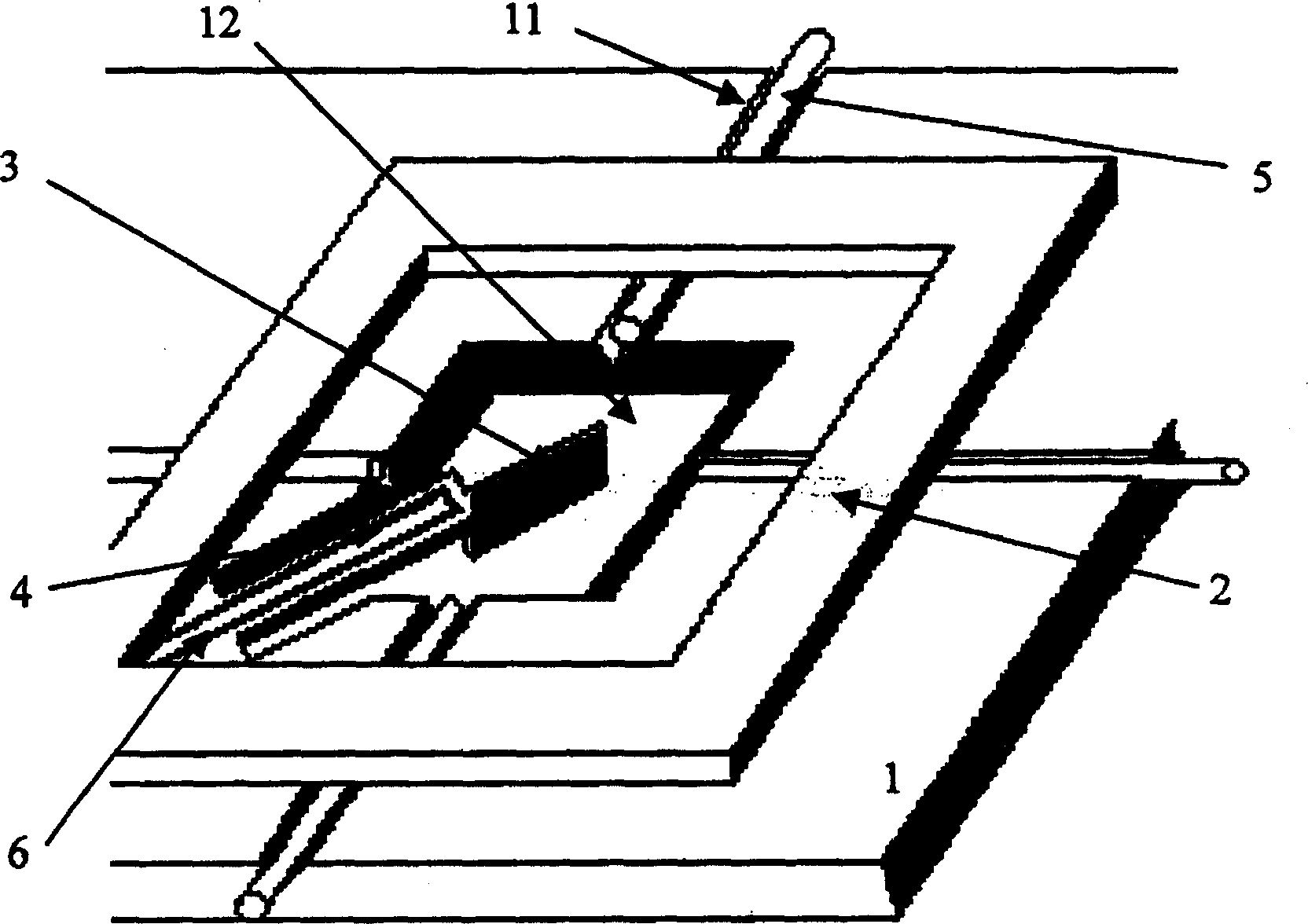
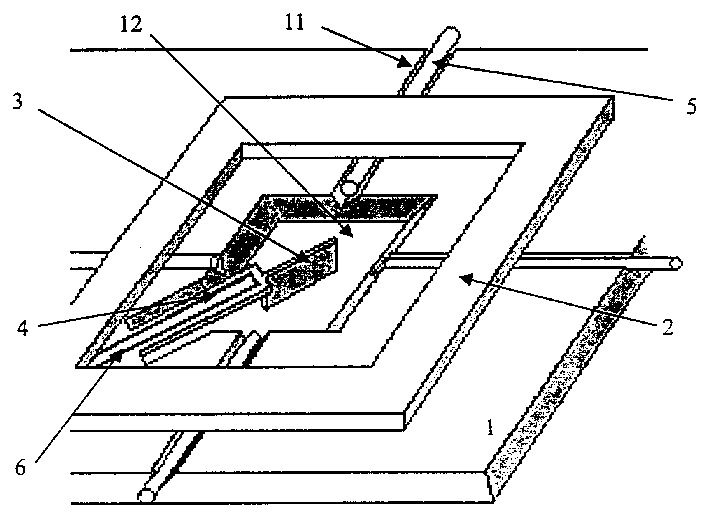
[0011] A heat-driven micromechanical optical fiber switch, the optical fiber switch is composed of a silicon plate 1 for fixing the optical fiber, a silicon plate 2 for pressing the optical fiber, a microreflector 3, a cantilever beam 4, an optical fiber 5, and a heating resistor 6. The surface of the silicon plate 1 is provided with 4 crosses with each other, adjacent vertical optical fiber grooves 11 are provided with optical fibers 5 in the grooves, a pit 12 is arranged in the center of the silicon plate 1 for fixing the optical fibers, and the reflector 3 is located In the pit 12, both sides of the mirror surface form an angle of 45 degrees with the four optical fibers 5, the reflector 3 is fixed on one end of the cantilever beam 4, and the other end of the cantilever beam 4 is connected to the silicon plate 1 on which the optical fiber is fixed, and pressed The silicon plate 2 of the optical fiber is pressed on the silicon plate 1 of the fixed optical fiber in a square fra...


PUM


Abstract

A thermally driven micromechanical switch for blocking or switching optical fibre signals in optical network is disclosed. 4 optical fibres perpendicular to each other are fixed on silicon board with a central pit for arranging a reflector in it. The said reflector with 45 deg of included angle relative to said optical fibres is fixed to one end of a cantilever whose another end is fixed to said silicon board. Its preparingp rocess includes corroding deep slots on the back of silicon board, corroding the silicon film at the position of cantilever, growing insulating film and metal film for making heating resistor, etching resistor bars, photoetching cantilever with reflector and optical fibre slots pattern, and corroding on front surface to form optical fibre slots, cantilever and microreflector.

Description

1. Technical field: [0001] The invention is a device for blocking and converting optical fiber signals in a digital optical fiber communication network, in particular a heat-driven micromechanical switch device and its manufacturing method. 2. Background technology: [0002] Realizing the Broadband Integrated Digital Communication Network (B-ISDN) which is the core of the next-generation communication network is one of the concerns of people, and expects to usher in the era of Fiber-to-the-Home (FTTH). The optical switch device is a key component to realize arbitrary cross-connection of optical fibers between users and switches, and is also one of the key devices to realize FTTH. The traditional mechanical optical switch is bulky, expensive and has poor reliability, which is difficult to meet the requirements of FTTH. Recently proposed electro-optic and waveguide switches improve some of these disadvantages, but their insertion loss and crosstalk are still large compared to...

Claims


Application Information

Patent Timeline
Patent Type & Authority Patents(China)
IPC IPC(8): G02B6/35
Inventor 秦明黄庆安樊路加
Owner SOUTHEAST UNIV
Why Eureka
Try Eureka