
Diaphragms for air springs and air springs

A technology of air springs and diaphragms, applied in the direction of gas shock absorbers, etc., to achieve the effect of expanding effective space, excellent appearance, and superior durability

Inactive Publication Date: 2018-05-25
NITTA CHEM IND PROD CO LTD
View PDF11 Cites 0 Cited by
  • Summary
  • Abstract
  • Description
  • Claims
  • Application Information

AI Technical Summary

Problems solved by technology

[0005] However, since various wiring or piping, a part of the vehicle frame, or a height adjustment device, various mechanisms or structures such as the interlocking mechanism between the trolley and the axle beam are provided around the air spring, it is considered that The design of the diameter expansion of the diaphragm is not necessarily feasible

Method used


Image

  • Diaphragms for air springs and air springs
  • Diaphragms for air springs and air springs
  • Diaphragms for air springs and air springs

Examples


Embodiment approach 1

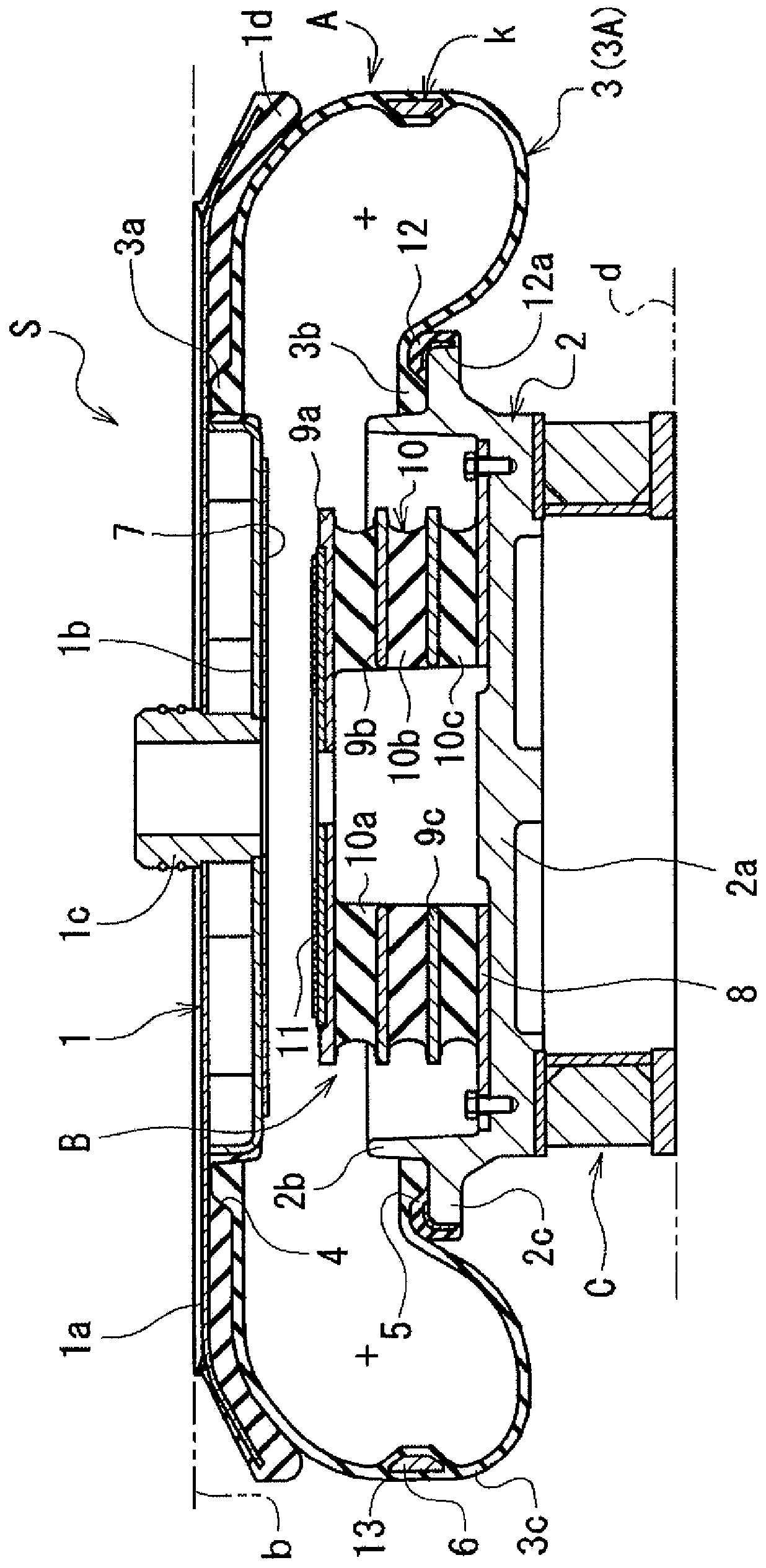
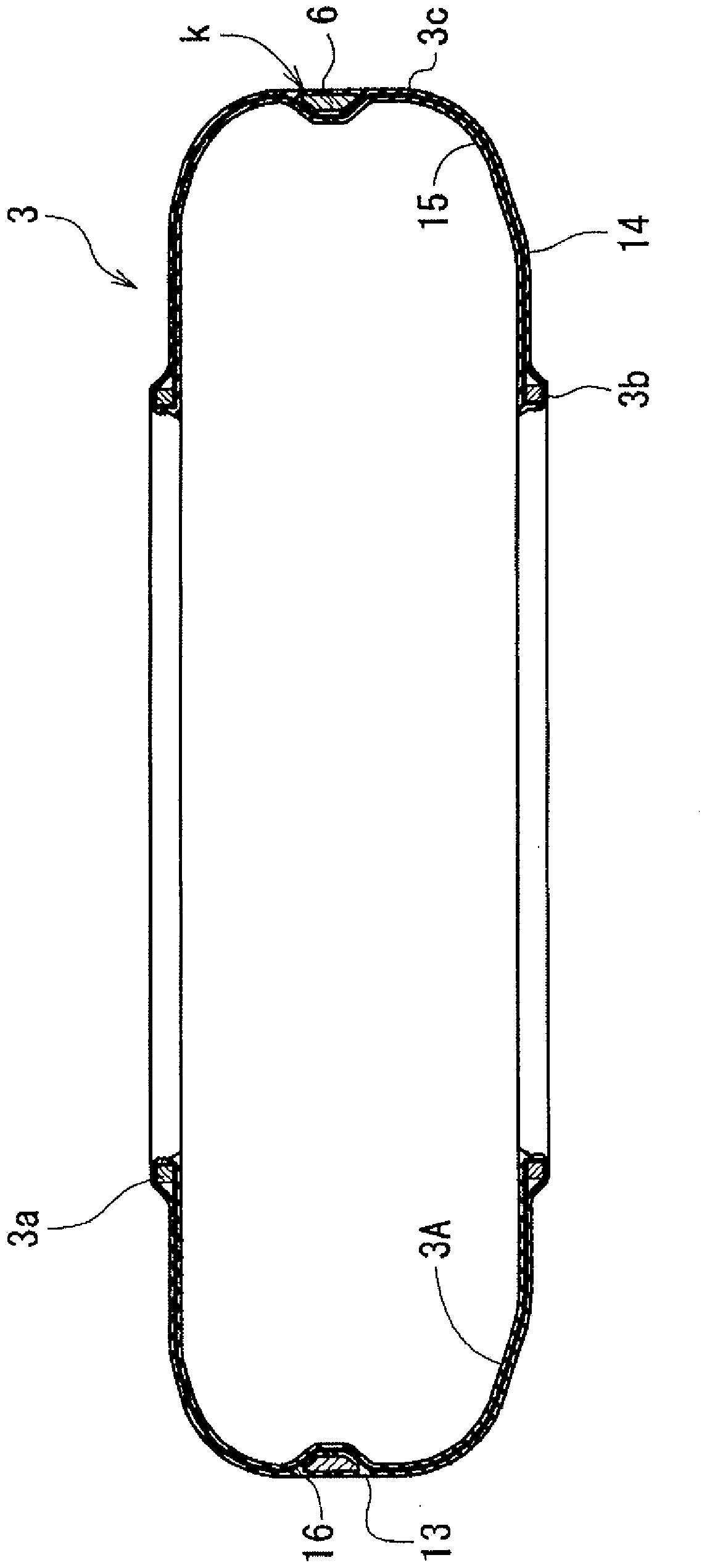
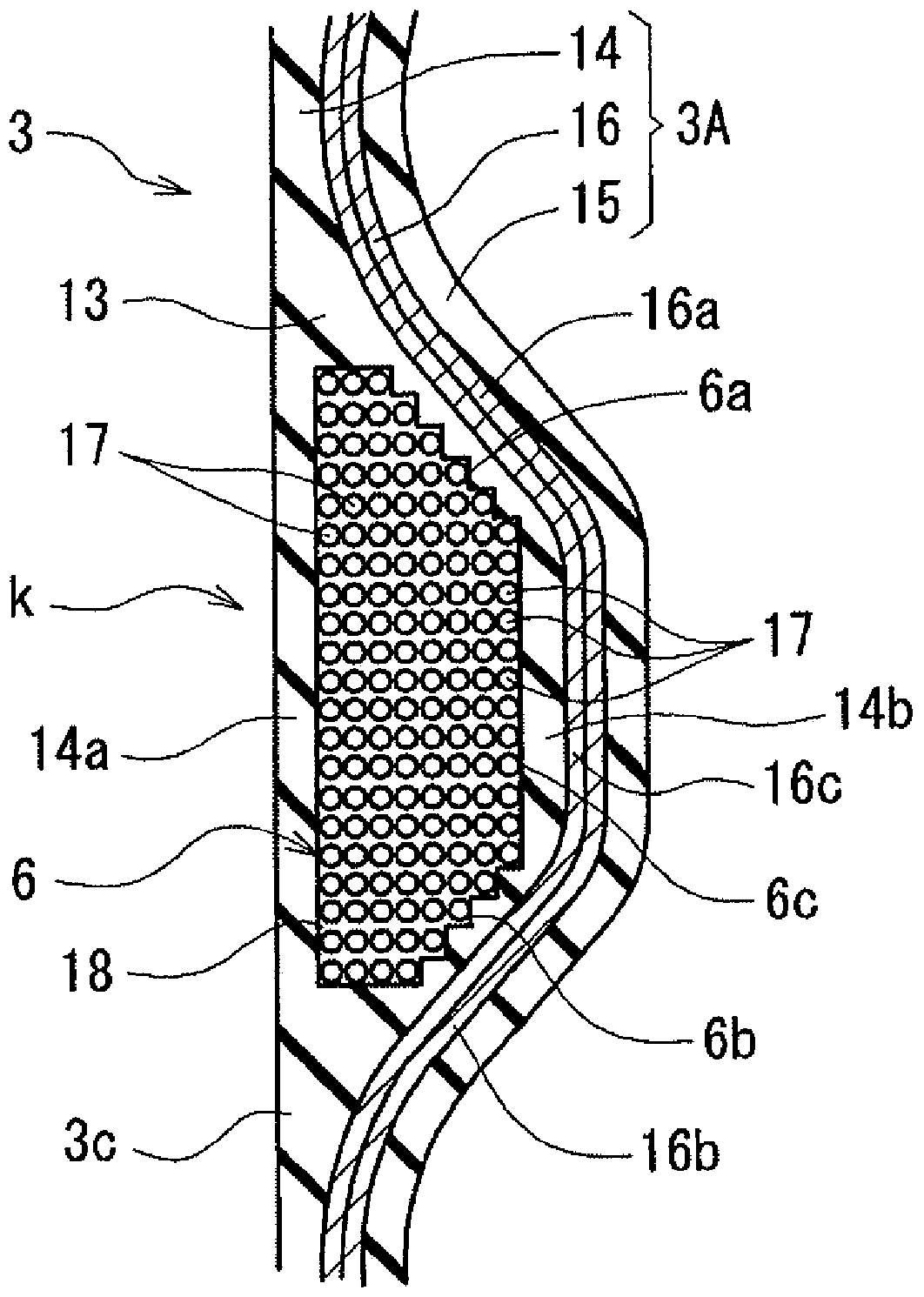
[0056] Hereinafter, the air spring A and the diaphragm 3 will be described in detail. Such as Figure 1-3 As shown, the constraining portion k in the air spring A is formed by embedding the reinforcing material 6 in the thick portion 13 formed by protruding and increasing the thickness of the elastic material forming the main body portion 3c radially inward.

[0057] The elastic material 3A forming the diaphragm 3 is an elastic film ( rubber film), and the thick wall portion 13 is formed by protruding and increasing the thickness of the outer rubber layer 14 inwardly in the radial direction, and the reinforcing material 6 is embedded in the thick wall portion 13 formed by the outer rubber layer 14 The state is set around.

[0058] Such as image 3 As shown, the reinforcing material 6 is formed by covering a core material 17 formed of a ring-shaped or spiral-shaped metal material (steel) or the like in plan view and covered with a protective layer 18 formed of rubber or the ...

Embodiment approach 2

[0069] The diaphragm for an air spring and the air spring according to Embodiment 2 are only different from the constraining portion k in Embodiment 1, Figure 5 Indicates its main part.

[0070] Such as Figure 5 As shown, the binding portion k has a reinforcing material 6 with a rectangular cross section. In the radially inner side of the reinforcing material 6 , the positional relationship between the upper and lower corner portions 6 d , 6 e and the radially outer side surface of the reinforcing cord layer 16 of the diaphragm 3 is in contact with or very close to. Except that it is the same as diaphragm 3 (air spring A) in Embodiment 1, Figure 5 , the corresponding reference signs are marked on the corresponding places.

[0071] According to the diaphragm 3 (air spring A) of any of the embodiments, due to the presence of the constraining portion k, an effective outer diameter restricting action can be obtained. In addition, in the diaphragm 3 (air spring A) of the sec...


PUM


Abstract

The invention provides an improved air spring which can restrain expanding of a membrane without actually expanding the diameter of the membrane or upsizing and requantizing an upper support part. The air spring is provided with an upper support part (1) on the side of a vehicle body, a lower support part (2) on the side of a trolley, a membrane (3) prepared by elastic materials (3A) from the upper support part (1) to the lower support part (2). A largest diameter part in the membrane (3) or the periphery thereof is winded by enforcement materials (6) so as to form a restraining part (k) which restrains the membrane (3) to prevent the membrane (3) from expanding over a prescribed value and projects to the radial inner side of the membrane (3). The restraining part (k) is formed by embedding the enforcement materials (6) in a thick wall part (13) which is formed by projecting to the radial inner side through the thickness of the elastic materials (3A).

Description

technical field [0001] The present invention relates to an air spring suitable for vehicles such as railway vehicles, and a diaphragm used for the air spring. Background technique [0002] As shown in Patent Document 1 and Patent Document 2, such an air spring includes an upper support portion on the vehicle body side, a lower support portion on the vehicle side, and an elastic material diaphragm provided from the upper support portion to the lower support portion. [0003] For example, air springs are often used in railway vehicles as suspension means, and are installed between the trolley and the upper and lower sides of the vehicle. [0004] In this case, the following shape changes can occur in the diaphragm of the air spring. That is, as the load increases due to the increase of passengers, etc., the vertical dimension decreases and the lateral dimension, that is, the diameter expands. Therefore, around the air spring, it is necessary to leave a space in consideration...

Claims


Application Information

Patent Timeline
Patent Type & Authority Patents(China)
IPC IPC(8): F16F9/04
Inventor 本多永二郎
Owner NITTA CHEM IND PROD CO LTD
Learn More