Transition section structure of reinforced concrete column and concrete filled steel tubular column and construction method

A technology for reinforced concrete columns and concrete-filled steel tubular columns, which is applied to structural elements, columns, piers, etc., can solve the problems of poor air circulation, welding of concrete-filled steel tubular columns, and inconvenient construction of welding workers, so as to avoid poisoning, improve project quality, The effect of improving convenience

Pending Publication Date: 2022-01-28
广西路建集团建筑工程有限公司
View PDF0 Cites 0 Cited by
  • Summary
  • Abstract
  • Description
  • Claims
  • Application Information

AI Technical Summary

Problems solved by technology

[0004] The present invention aims to solve the above-mentioned technical problems, and provides a transition section structure and construction method between a reinforced concrete column and a concrete-filled steel tube column, which mainly solves the problem of insufficient light and air circulation in a steel-filled concrete column, which causes inconvenience to welders during construction and the construction of a reinforced concrete column. The technical problem that the displaced steel bars are difficult to adjust and cannot be welded to the steel tube concrete column

Method used


Image

  • Transition section structure of reinforced concrete column and concrete filled steel tubular column and construction method
  • Transition section structure of reinforced concrete column and concrete filled steel tubular column and construction method

Examples


Embodiment

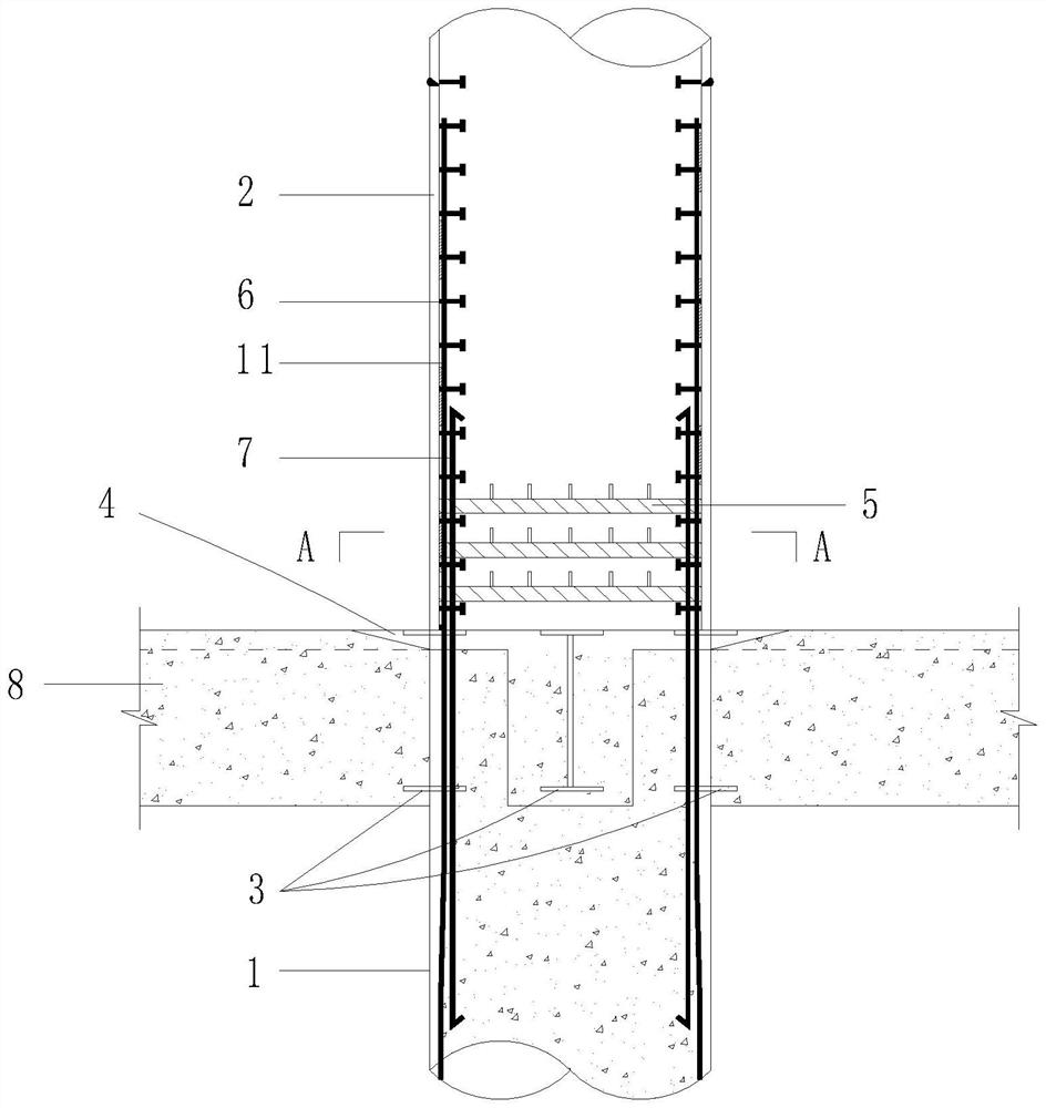
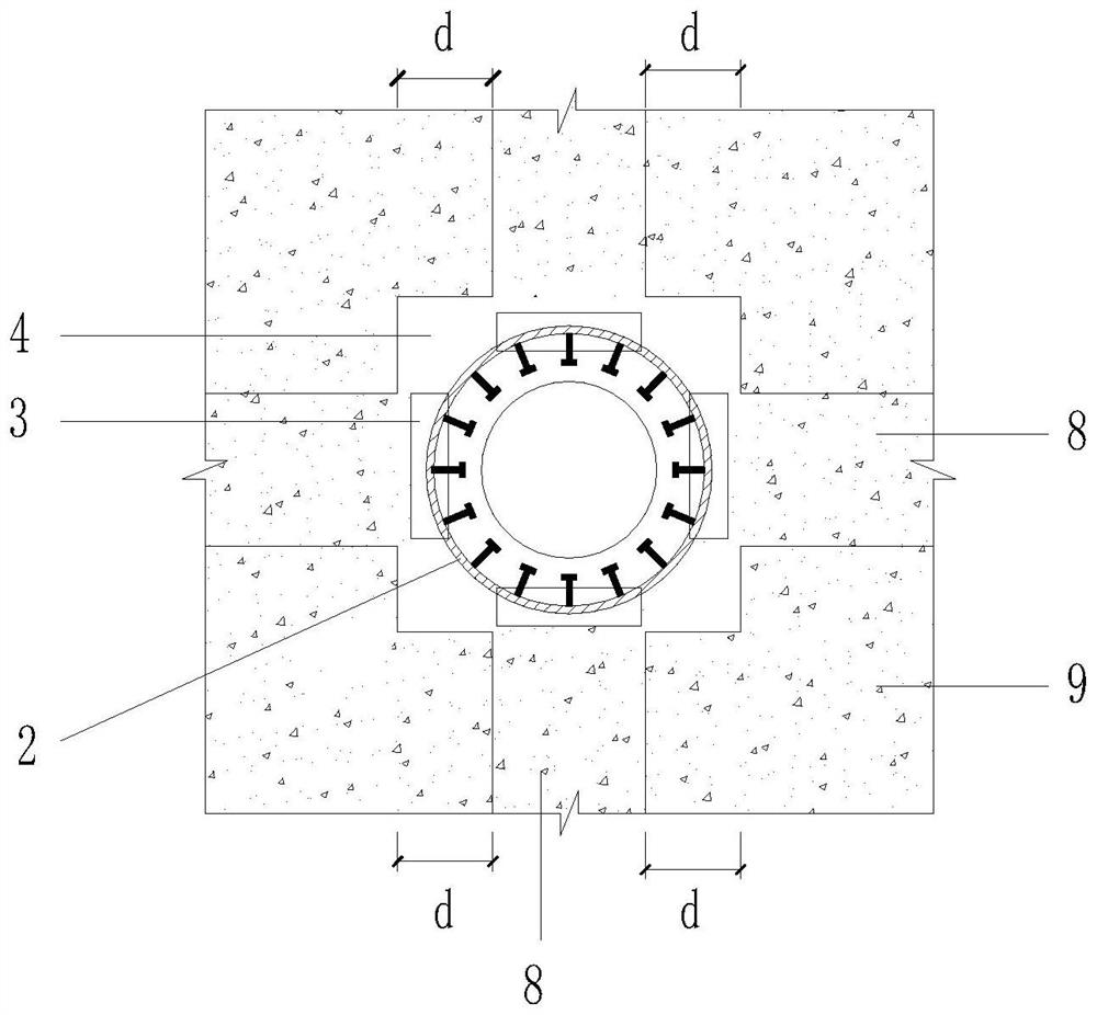
[0034] Such as figure 1 and figure 2 As shown, the transition section structure between reinforced concrete column and steel pipe concrete column includes reinforced concrete column 1, steel pipe concrete column 2, I-beam 3, reinforced concrete beam 8 and reinforced concrete slab 9, and reinforced concrete column 1 runs through the steel bar from bottom to top Concrete beam 8, and the upper end surface of reinforced concrete column 1 is flush with the upper end surface of reinforced concrete beam 8, I-shaped steel 3 is vertically pre-buried on the upper part of reinforced concrete column 1, and the upper end surface of I-shaped steel 3 is aligned The upper end of the column 1 is flush, the lower end of the steel tube concrete column 2 is welded to the upper end of the I-beam 3, and the upper end of the reinforced concrete beam 8 and reinforced concrete slab 9 near the reinforced concrete column 1 is reserved with post-casting concrete sections. Specifically, the post-poured ...


PUM


Abstract

The invention belongs to the technical field of constructional engineering, and particularly relates to a transition section structure of a reinforced concrete column and a concrete filled steel tubular column and a construction method.The transition section structure of the reinforced concrete column and the concrete filled steel tubular column comprises the reinforced concrete column, the concrete filled steel tubular column, I-shaped steel, a reinforced concrete beam and a reinforced concrete slab. The reinforced concrete column runs from the bottom up through reinforced concrete beam and the reinforced concrete slab; the I-shaped steel is vertically embedded in the upper portion of the reinforced concrete column, and the upper end face of the I-shaped steel is flush with the upper end face of the reinforced concrete column; and the lower end of the concrete filled steel tubular column is welded to the upper end of the I-shaped steel, and post-pouring concrete sections are reserved on the upper end faces of the reinforced concrete beam and the reinforced concrete slab close to the reinforced concrete column. The problems that light in the concrete filled steel tubular column is insufficient, air does not circulate, and great potential safety hazards exist when workers weld steel bars are solved; the operation space environment in the concrete filled steel tubular column is improved, safety of operators is guaranteed, and construction efficiency is improved.

Description

technical field [0001] The invention belongs to the technical field of construction engineering, and in particular relates to a transition section structure and a construction method of a reinforced concrete column and a steel tube concrete column. Background technique [0002] At present, the conventional method for the construction of the transition section between the reinforced concrete column and the concrete-filled steel tube column is to weld the steel bars of the transition section after pouring the reinforced concrete beam column of the lower section and the concrete at the floor, and then temporarily fix the concrete-filled steel column column of the upper section to the floor. After the completion, the concrete of the upper concrete-filled steel tube column will be poured. The disadvantage of this method is that there are a large number of additional steel bars in the transition section, and the longitudinal bars extending from the lower reinforced concrete column...

Claims


Application Information

Patent Timeline
Patent Type & Authority Applications(China)
IPC IPC(8): E04B1/20E04B1/21E04B1/41E04C3/34E04C5/16E04G21/00E04G21/02
CPCE04B1/20E04B1/21E04B1/41E04C3/34E04C5/16E04G21/00E04G21/02E04B1/215
Inventor 陈远黄后玉黄善毅张媛媛梁冬瑶梁应偶卢晓君戴文广李昀霓
Owner 广西路建集团建筑工程有限公司
Why Eureka
Try Eureka