


Quick Research
Generate reliable direction feasibility study reports for your R&D in just a few steps.

Technical Q&A
Discover and master advanced knowledge NOW. Basics, ideas, possibilities, all at once.

Find Solutions
As an expert in R&D theories, this can generate solutions to your technical problems instantly.

Evaluate Feasibility
Analyze your overall solution with one click, know your potential R&D risks in advance.

Monitor Landscape
Get weekly tech updates, stay abreast of the latest tech innovations and key insights.
Method for recovering 14C in 14C-containing exhaust gas
A technology of 14CO2 and exhaust gas, applied in separation methods, chemical instruments and methods, separation of different isotopic elements, etc., can solve problems such as difficult recovery
- Summary
- Abstract
- Description
- Claims
- Application Information
AI Technical Summary
Problems solved by technology
Method used
Image

Examples
Embodiment 1
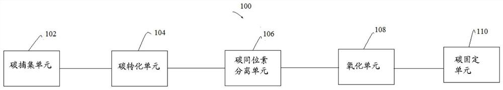
[0191] A method for recovering 14C in waste gas containing 14C, including:
[0192] a) Capture CO in exhaust gas containing 14C 2 , to obtain rich CO 2 gas
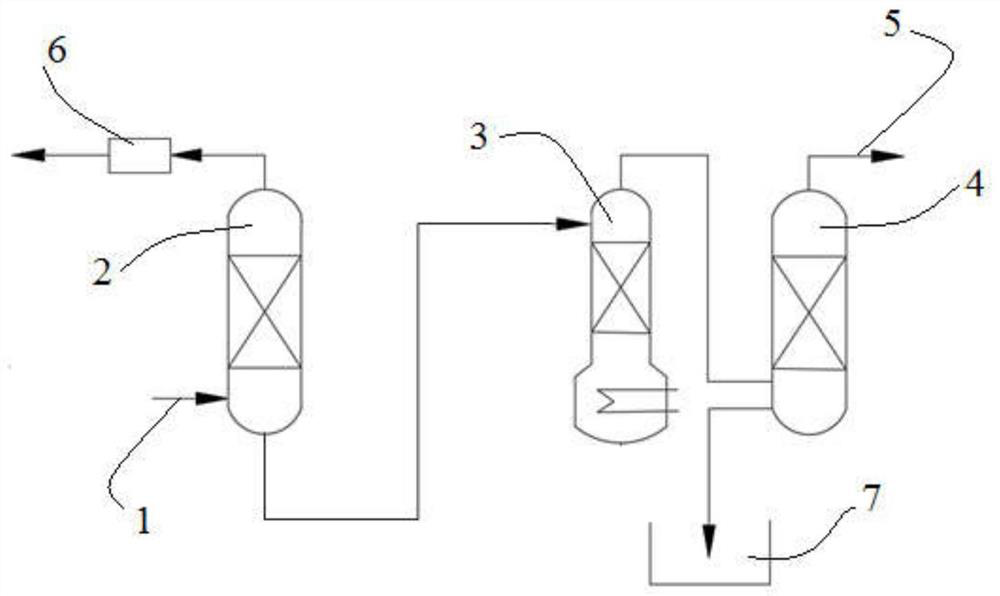
[0193] use figure 2 The carbon capture unit shown performs this step a). Specifically, the waste gas containing 14C (14CO 2 Content is 2×10 -12 v / v) Enter the first absorption tower 2 through the first feed port 1, and contact with the absorbent (ammonia solution) in the first absorption tower 2 to generate flue gas and absorb CO 2 of the absorbent. The flue gas is discharged from the top of the absorption tower 2 into the adsorption device 6, and is discharged after being adsorbed by activated carbon in the adsorption device 6. will absorb CO 2 The absorbed liquid is transported to the regeneration tower 3, and the regeneration gas mixture is generated after being regenerated by the regeneration tower. The regeneration gas mixture is sent to the second absorption tower 4 (i.e. ammonia absorption tower) for abso...
Embodiment 2
[0203] It is basically the same as above-mentioned embodiment 1, and the difference is only that its step a) adopts the following scheme:
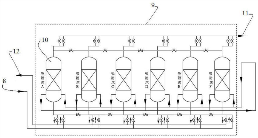
[0204] use image 3 The carbon capture unit shown performs this step a). Specifically, the waste gas containing 14C (14CO 2 Content is 2×10 -12 v / v) Enter the adsorption device 9 through the second feed port 8. The adsorption device 9 is composed of 6 adsorption beds 10. The adsorption device 9 is configured to implement a combination of vacuum and temperature rise, so that the 14C-containing waste gas and the selective adsorption of CO 2 The adsorbent (zeolite molecular sieve) is contacted in the adsorption bed 10 to obtain the adsorbed adsorbent and remove the gas that is not adsorbed by the adsorbent, and then desorb the adsorbed adsorbent to obtain CO-enriched 2 Gas (CO 2 Content ≥ 99.5% by volume). The gas that is not adsorbed by the adsorbent is output through the second outlet 11, rich in CO 2 The gas is exported through the t...
Embodiment 3
[0206] It is basically the same as above-mentioned embodiment 1, and the difference is only that its step e) adopts the following scheme:
[0207] use Figure 8 The illustrated stationary unit performs this step e). Specifically, the eighth feed port 26 is in fluid communication with the ninth feed port 29, so that 14CO-rich 2 The gas enters the fourth absorption tower 30 through the ninth feed port 29, and reacts with the sodium hydroxide solution in the fourth absorption tower 30 to generate a sodium carbonate solution. The sodium carbonate solution is sent to the first scrubber 31, and the calcium hydroxide and the sodium carbonate solution are reacted in the first scrubber 31, so as to obtain a slurry containing calcium carbonate precipitate. The slurry containing the precipitated calcium carbonate is sent to the filtering device 32 for filtering the slurry containing the precipitated calcium carbonate to recover the filtrate and obtain a filter cake that can be used as ...
PUM
 Abstract
Description
Claims
Application Information
 - R&D Engineer
- R&D Manager
- IP Professional
- Industry Leading Data Capabilities
- Powerful AI technology
- Patent DNA Extraction
Browse by: Latest US Patents, China's latest patents, Technical Efficacy Thesaurus, Application Domain, Technology Topic, Popular Technical Reports.
© 2024 PatSnap. All rights reserved.Legal|Privacy policy|Modern Slavery Act Transparency Statement|Sitemap|About US| Contact US: help@patsnap.com