Circular pipe cutting equipment for building
A technology for cutting equipment and construction, applied in metal sawing equipment, metal processing equipment, sawing machine devices, etc., can solve the problem of slow cutting speed of round pipes
- Summary
- Abstract
- Description
- Claims
- Application Information
AI Technical Summary
Problems solved by technology
Method used
Image
Examples
Embodiment 1
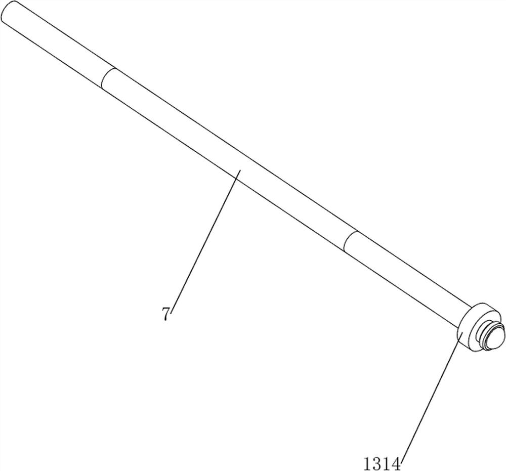
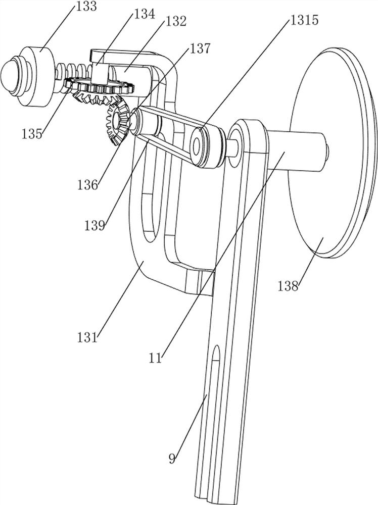
[0032] A circular pipe cutting equipment for construction, such as figure 1 As shown, it includes a support plate 1, a first support frame 2, a cylinder 3, a fixed frame 4, a second support frame 5, a motor 6, a first rotating shaft 7, an electric saw 8, a third support frame 9, and a first rotating frame 10, the first fixed rod 11, the manual unloading mechanism 12 and the rotating mechanism 13, the first support frame 2 is provided on the front side of the top of the support plate 1, the cylinder 3 is provided on the first support frame 2, and the telescopic rod of the cylinder 3 is provided with There is a fixed frame 4, the left side of the fixed frame 4 rear portion is provided with a second support frame 5, the second support frame 5 is provided with a motor 6, the right side of the output shaft of the motor 6 is provided with a first rotating shaft 7, and the left side of the first rotating shaft 7 There is an electric saw 8 at the top, and the electric saw 8 is located...
Embodiment 2
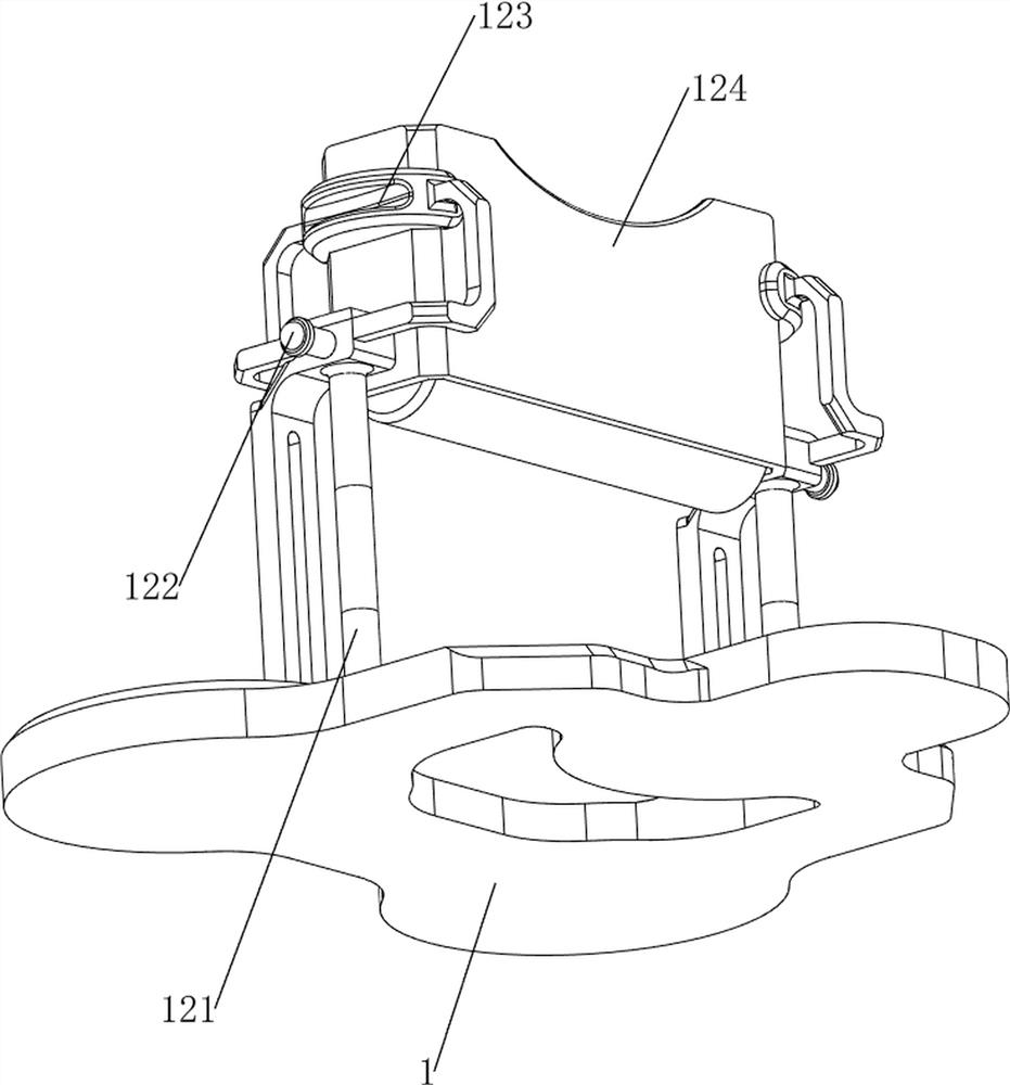
[0035] On the basis of Example 1, such as Figure 1-5As shown, the manual unloading mechanism 12 includes a fourth support frame 121, a second rotating frame 122, a fifth support frame 123 and a blanking frame 124, and the left and right symmetry in the middle of the top of the support plate 1 is provided with the fourth support frame 121. The second rotating frame 122 is connected between the four supporting frames 121, the fifth supporting frame 123 is arranged on the fourth supporting frame 121, and the blanking frame 124 is connected between the fifth supporting frames 123 on both sides, and the second rotating frame 122 is located directly below the blanking frame 124.
[0036] The user can place the round tubes that need to be cut in the blanking frame 124, and the round tubes in the blanking frame 124 will drop down in the second rotating frame 122, and the second rotating frame 122 can only accommodate one round tube. tube, when it is necessary to unload the first rot...
Embodiment 3
[0040] On the basis of Example 2, such as figure 1 and Figure 6-12 As shown, an automatic unloading mechanism 14 is also included, and the automatic unloading mechanism 14 includes a first fixed plate 141, a second spring 142, a ratchet bar 143, a ratchet gear 144, a first torsion spring 145, and a second fixed rod 146 and the third fixed rod 147, the middle of the fourth support frame 121 outer sides are provided with a first fixed plate 141, and the first fixed plate 141 is slidably provided with a connecting rod, and a second fixed plate 141 is connected between the connecting rod and the first fixed plate 141 Two springs 142 are provided with a ratchet bar 143 slidingly on the connecting rod, and the left and right sides of the second rotating frame 122 are provided with a ratchet gear 144. 122 are connected with a first torsion spring 145, the bottom of the connecting rod is connected with a second fixed rod 146, and the left and right sides of the telescopic rod of the...
PUM
 Abstract
Description
Claims
Application Information
 - Generate Ideas
- Intellectual Property
- Life Sciences
- Materials
- Tech Scout
- Unparalleled Data Quality
- Higher Quality Content
- 60% Fewer Hallucinations
Browse by: Latest US Patents, China's latest patents, Technical Efficacy Thesaurus, Application Domain, Technology Topic, Popular Technical Reports.
© 2025 PatSnap. All rights reserved.Legal|Privacy policy|Modern Slavery Act Transparency Statement|Sitemap|About US| Contact US: help@patsnap.com


