Green Chinese onion root hair removing equipment for agricultural production
A technology for scallions and equipment, which is applied in the field of equipment for removing scallions roots for agricultural production, and can solve the problems of slow cutting speed of scallions
- Summary
- Abstract
- Description
- Claims
- Application Information
AI Technical Summary
Problems solved by technology
Method used
Image
Examples
Embodiment 1
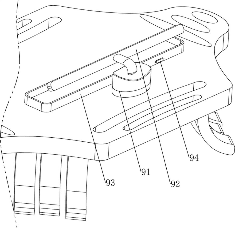
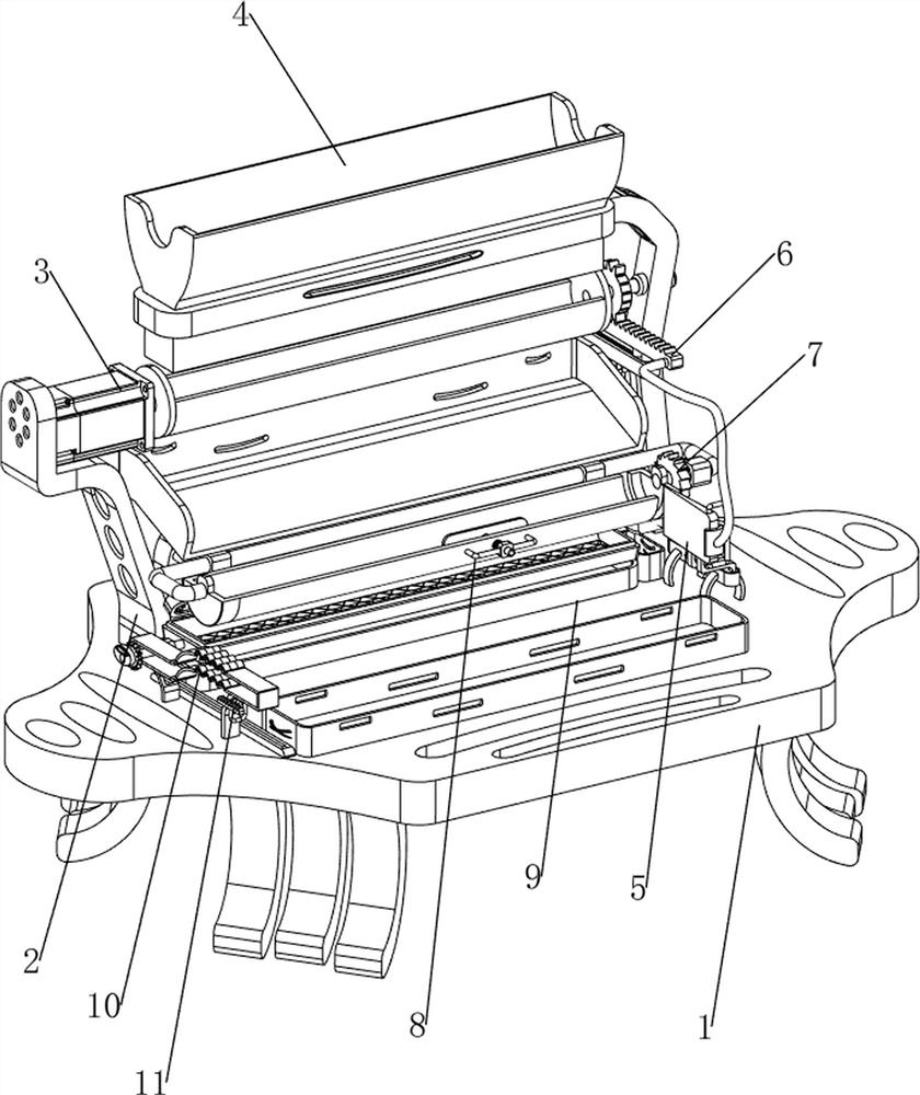
[0031] A kind of equipment for removing scallion roots for agricultural production, such as figure 1 As shown, it includes a base plate 1, a base 2, a servo motor 3, a feeding mechanism 4 and a manual cutting mechanism 5. The base 2 is provided on the rear side of the upper part of the base plate 1, and the servo motor 3 is provided on the left side of the upper part of the base 2. The rear side of the upper part of the base plate 1 A blanking mechanism 4 is provided on the side, and a manual cutting mechanism 5 is provided on the right side of the upper part of the bottom plate 1 .
[0032] When the user needs to cut off the root of the green onion, this device can be used. First, the green onion that needs to be cut off the root is placed in the feeding mechanism 4, and then the servo motor 3 is started, and the servo motor 3 will drive the feeding mechanism 4 to operate. Then by manually controlling the cutting mechanism 5, the root of the green onion is cut. After the cutt...
Embodiment 2
[0034] On the basis of Example 1, such as figure 2 and image 3 As shown, the blanking mechanism 4 includes a first support frame 41, a blanking frame 42, a first rotating shaft 43, a first loading frame 44, a first support 45, a slide plate 46, a second support frame 47, and a second rotating shaft 48 , discharge frame 49, connecting plate 410 and rubbish frame 411, base plate 1 top right rear side is provided with first support frame 41, and first support frame 41 left side is connected with blanking frame 42, and first support frame 41 upper rotary type A first rotating shaft 43 is provided, a first charging frame 44 is connected between the first rotating shaft 43 and the output shaft of the servo motor 3, and a first bracket 45 is arranged symmetrically on the rear side of the upper part of the bottom plate 1, and the first brackets on both sides 45 tops are connected with a slide plate 46, the first support 45 is provided with a second support frame 47, the right side ...
Embodiment 3
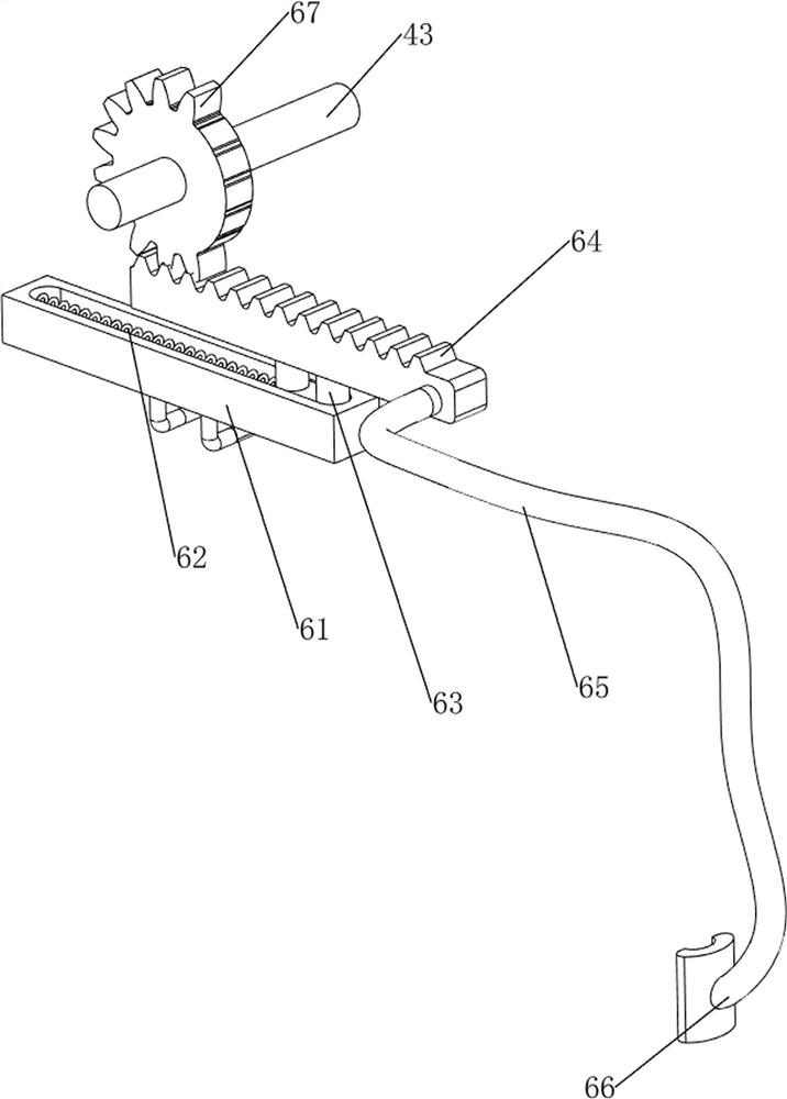
[0039] On the basis of Example 2, such as Figure 4-9 As shown, an automatic cutting mechanism 6 is also included, and the automatic cutting mechanism 6 includes a second slide rail 61, a second spring 62, a second slider 63, a first rack 64, a second bracket 65, a push plate 66 and a second A gear 67, the first support frame 41 is connected with a second slide rail 61, and the second slide rail 61 is slidably provided with a second slide block 63, and the second slide block 63 and the second slide rail 61 are connected with a second slide rail 61. Two springs 62, a first rack 64 connected to the top of the second slider 63, a second bracket 65 connected to the front side of the first rack 64, a push plate 66 is provided on the second bracket 65, and a push plate 66 is provided on the first rotating shaft 43. The first gear 67 is meshed with the first rack 64 .
[0040] The rotation of the first rotating shaft 43 drives the first gear 67 to rotate, and the first gear 67 meshe...
PUM
 Abstract
Description
Claims
Application Information
 - R&D Engineer
- R&D Manager
- IP Professional
- Industry Leading Data Capabilities
- Powerful AI technology
- Patent DNA Extraction
Browse by: Latest US Patents, China's latest patents, Technical Efficacy Thesaurus, Application Domain, Technology Topic, Popular Technical Reports.
© 2024 PatSnap. All rights reserved.Legal|Privacy policy|Modern Slavery Act Transparency Statement|Sitemap|About US| Contact US: help@patsnap.com


