Wire stripper capable of removing impurities for optical cable installation
An installation and wire stripper technology, applied in the coupling of optical waveguides, light guides, optics, etc., can solve the problems of inability to automatically cut optical cables, incapable of automatic optical cables, and incapable of automatic optical cable surface skin and coating layer, etc.
- Summary
- Abstract
- Description
- Claims
- Application Information
AI Technical Summary
Problems solved by technology
Method used
Image
Examples
Embodiment 1
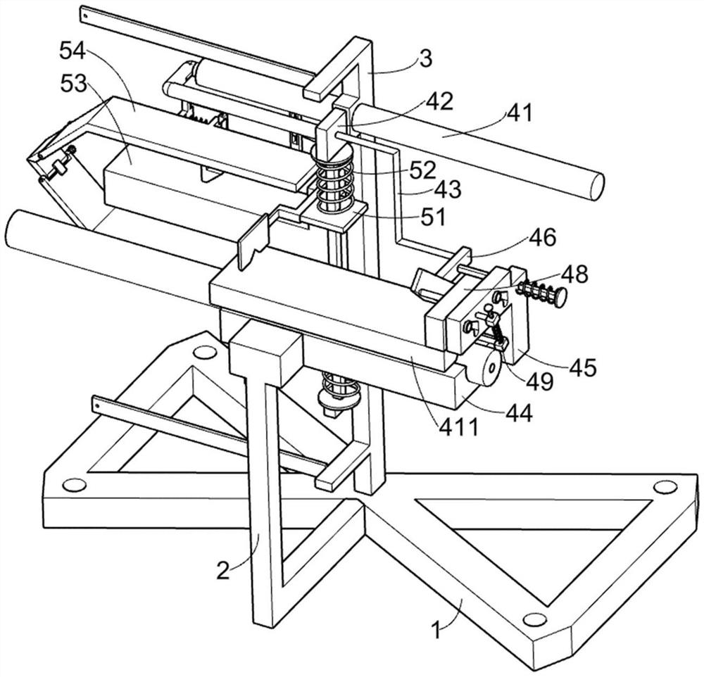
[0027] A wire stripper for optical cable installation that can remove impurities such as Figure 1-9 As shown, it includes a mounting chassis 1, a first support frame 2, a second support frame 3, an anti-deviation component 4 and a stripping component 5, the first support frame 2 is installed on one side of the mounting chassis 1, and the mounting chassis 1. The second support frame 3 is welded on the top, and the anti-deflection component 4 is arranged on the second support frame 3. The anti-deflection component 4 is used to prevent the optical cable on the lower limit block 44 from being deflected during processing. The component 5 is arranged on the anti-deviation component 4 , and the stripping component 5 is used to scrape off the skin and coating layer on the surface of the optical cable outside the lower limit block 44 .
[0028]The anti-deflection assembly 4 includes an electric push rod 41, a first push frame 42, a second push frame 43, a lower limit block 44, a third...
Embodiment 2
[0035] On the basis of Example 1, such as Figure 8-9 As shown, it also includes a wiping assembly 6. The wiping assembly 6 is arranged on the anti-deviation assembly 4. The wiping assembly 6 is used to clean up the impurities on the stripped optical cable. The wiping assembly 6 includes a support plate 61, a fifth support Frame 62, the 6th spring 63, wiping block 64 and stop frame 65, support plate 61 are symmetrically installed on the first push frame 42, and distribution vertically has three fifth support frames 62 on the support plate 61, on the 5th support frame 62 A sixth spring 63 is connected, and the other end of the sixth spring 63 is connected to the support plate 61. The sixth spring 63 is used to drive the fifth support frame 62 to move toward each other. The bottom of the fifth support frame 62 is connected with a wiper block 64. The wiping block 64 is used to clean up the impurities on the stripped optical cable. The blocking frame 65 is symmetrically connected ...
Embodiment 3
[0040] On the basis of Example 2, such as figure 1 As shown, it also includes an L-shaped protective plate 8, the bottom of the lower limit block 44 and the top of the upper limit block 411 are connected with an L-shaped protective plate 8, and the L-shaped protective plate 8 is used to prevent the optical cable on the lower limit block 44 from being damaged. The hand is pinched during processing, and the L-shaped protective plate 8 below is fixedly connected to the first support frame 2 .
[0041] The L-shaped protective plate 8 can prevent people's hands from being pinched when processing the optical cable on the lower limit block 44, so as to protect the safety of the operator.
PUM
 Abstract
Description
Claims
Application Information
 - R&D Engineer
- R&D Manager
- IP Professional
- Industry Leading Data Capabilities
- Powerful AI technology
- Patent DNA Extraction
Browse by: Latest US Patents, China's latest patents, Technical Efficacy Thesaurus, Application Domain, Technology Topic, Popular Technical Reports.
© 2024 PatSnap. All rights reserved.Legal|Privacy policy|Modern Slavery Act Transparency Statement|Sitemap|About US| Contact US: help@patsnap.com


