Cement dustproof screening equipment for building construction
A technology for building construction and screening equipment, which is applied in the direction of screening, solid separation, grille, etc., can solve the problems of low efficiency of cement screening, inconvenient cement screening, affecting the smoothness of the wall, etc., and achieve the effect of improving screening efficiency
- Summary
- Abstract
- Description
- Claims
- Application Information
AI Technical Summary
Problems solved by technology
Method used
Image
Examples
Embodiment 1
[0035] A kind of cement dust-proof screening equipment for building construction, such as figure 1 As shown, it includes a screening box 1, a support plate 2, a backing plate 3, a screening mechanism 4, and a driving mechanism 5. The front, rear, left, and right sides of the bottom of the screening box 1 are equipped with a support plate 2, and the bottom of the support plate 2 is equipped with a backing plate. 3. A screening mechanism 4 is installed on the screening box 1, and a driving mechanism 5 is installed on the top of the screening box 1, and the driving mechanism 5 cooperates with the screening mechanism 4.
[0036] When the cement needs to be screened, the user pours the cement into the screening box 1, and then the cement poured into the screening box 1 falls down on the screening mechanism 4, and then the user starts the driving mechanism 5 to work, and the driving mechanism 5 can work Make the screening mechanism 4 work, and the screening mechanism 4 can screen th...
Embodiment 2
[0038] On the basis of Example 1, such as figure 1 , figure 2 , image 3 and Figure 4 As shown, the screening mechanism 4 includes a fixed plate 401, a buffer spring 402, a contact plate 403, a screen mesh plate 404, a feeding pipe 405, a screen frame 407 and a first spring 408, and the fixed plate 401 is provided with four, all connected On the left and right side walls in the screening box 1, a buffer spring 402 is installed on the top of the fixed plate 401, the top of the buffer spring 402 is fixedly connected with a contact plate 403, and a screen mesh plate 404 is arranged between the tops of the four contact plates 403, The top right side of the screening box 1 is embedded with a feeding pipe 405, and the lower part of the right side wall of the screening box 1 has a discharge port 406, and the sliding type in the discharge port 406 is provided with a screening grid 407, and the left part of the screening grid 407 Through the screening box 1 , a plurality of first ...
Embodiment 3
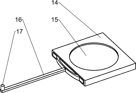
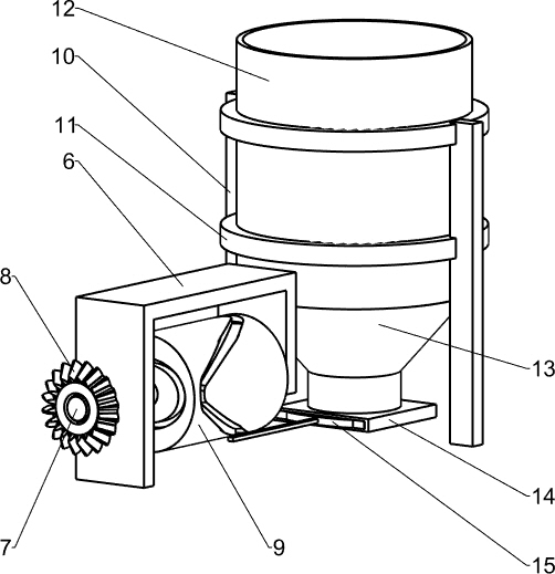
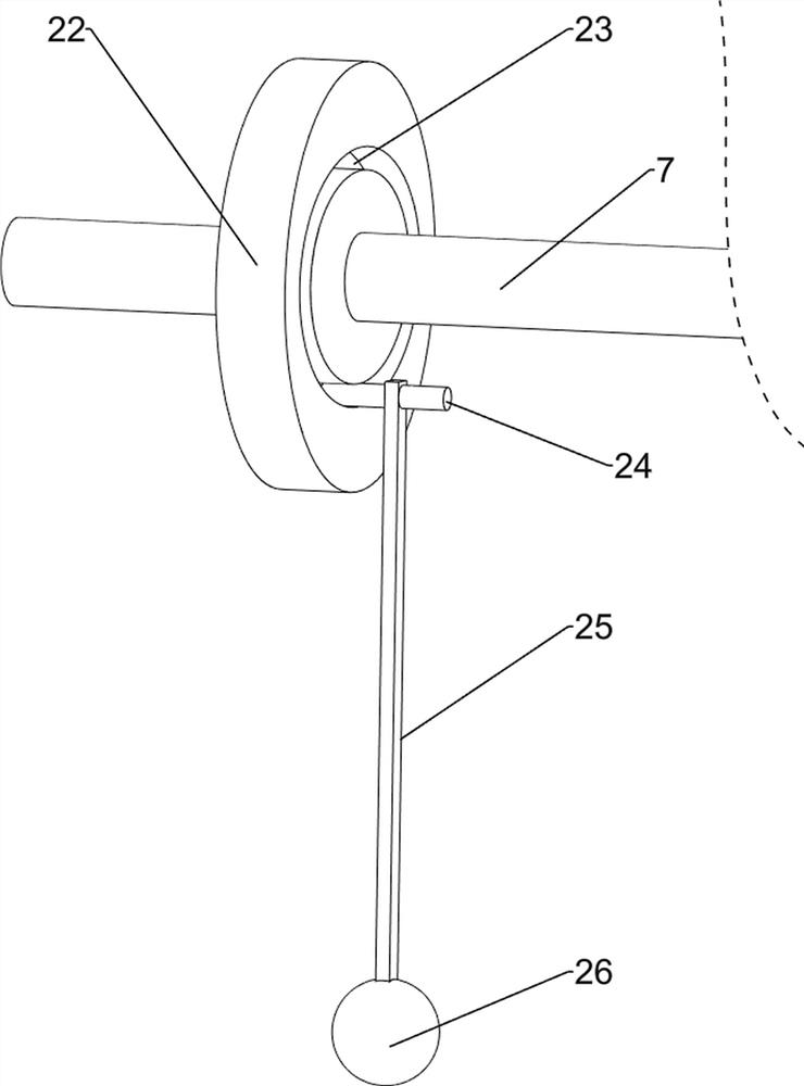
[0043] On the basis of Example 2, such as Figure 6 and Figure 7 As shown, it also includes a fixed frame 6, a second rotating shaft 7, a third bevel gear 8, a grooved roller 9, a support plate 10, a fixed ring 11, a lower barrel 12, a lower hopper 13, a first housing 14, a second A baffle plate 15, connecting rod 16 and slide block 17, the top of the screening box 1 is equipped with a fixed mount 6, the fixed mount 6 is located on the right side of the reduction motor 512, and the top of the fixed mount 6 is rotatably equipped with a second rotating shaft 7, the first The left end of the second rotating shaft 7 is equipped with a third bevel gear 8, the third bevel gear 8 meshes with the second bevel gear 513, grooved rollers 9 are installed on the second rotating shaft 7, and supports are installed on the front and rear sides of the screen box 1 top. Plate 10, two fixed rings 11 are fixedly connected between the tops of the front and rear two support plates 10, a lower mat...
PUM
 Abstract
Description
Claims
Application Information
 - Generate Ideas
- Intellectual Property
- Life Sciences
- Materials
- Tech Scout
- Unparalleled Data Quality
- Higher Quality Content
- 60% Fewer Hallucinations
Browse by: Latest US Patents, China's latest patents, Technical Efficacy Thesaurus, Application Domain, Technology Topic, Popular Technical Reports.
© 2025 PatSnap. All rights reserved.Legal|Privacy policy|Modern Slavery Act Transparency Statement|Sitemap|About US| Contact US: help@patsnap.com


