
Permanent magnet ring, motor applying permanent magnet ring and manufacturing method and mold

A manufacturing method and technology of permanent magnet rings, which are applied in the manufacture of inductors/transformers/magnets, motor generators, stator/rotor bodies, etc., can solve the problems of complex structure, difficult assembly and operation, and heavy motor rotors.

Pending Publication Date: 2022-01-21
江门市邦特电子电器有限公司
View PDF5 Cites 0 Cited by
  • Summary
  • Abstract
  • Description
  • Claims
  • Application Information

AI Technical Summary

Problems solved by technology

[0005] Existing problems of existing permanent magnet motors are as follows: (1) in order to adopt a non-magnetic material shell such as plastic, the magnetic ring must be equipped with a magnetic outer ring, which has a complex structure, a large number of parts, a long process flow, and difficult assembly operations; (2) With magnetic materials such as steel, the motor rotor itself is bulky, slow to start, and high in energy consumption; (3) Due to material and material process limitations (such as stamping or turning of the steel shell), the cost of the motor is high

Method used


Image

  • Permanent magnet ring, motor applying permanent magnet ring and manufacturing method and mold
  • Permanent magnet ring, motor applying permanent magnet ring and manufacturing method and mold
  • Permanent magnet ring, motor applying permanent magnet ring and manufacturing method and mold

Examples


Embodiment Construction

[0042] In order to enable those skilled in the art to better understand the solutions of the present invention, the technical solutions in the embodiments of the present invention will be clearly and completely described below in conjunction with the drawings in the embodiments of the present invention.

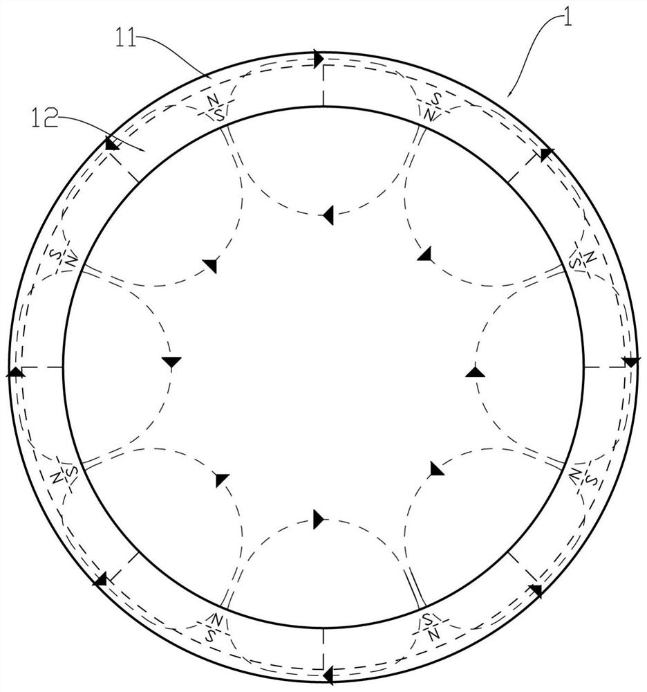
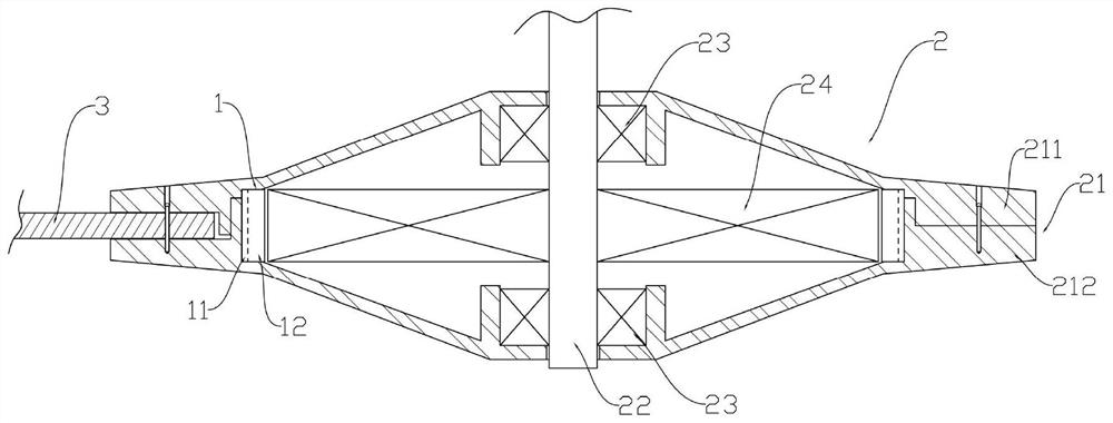
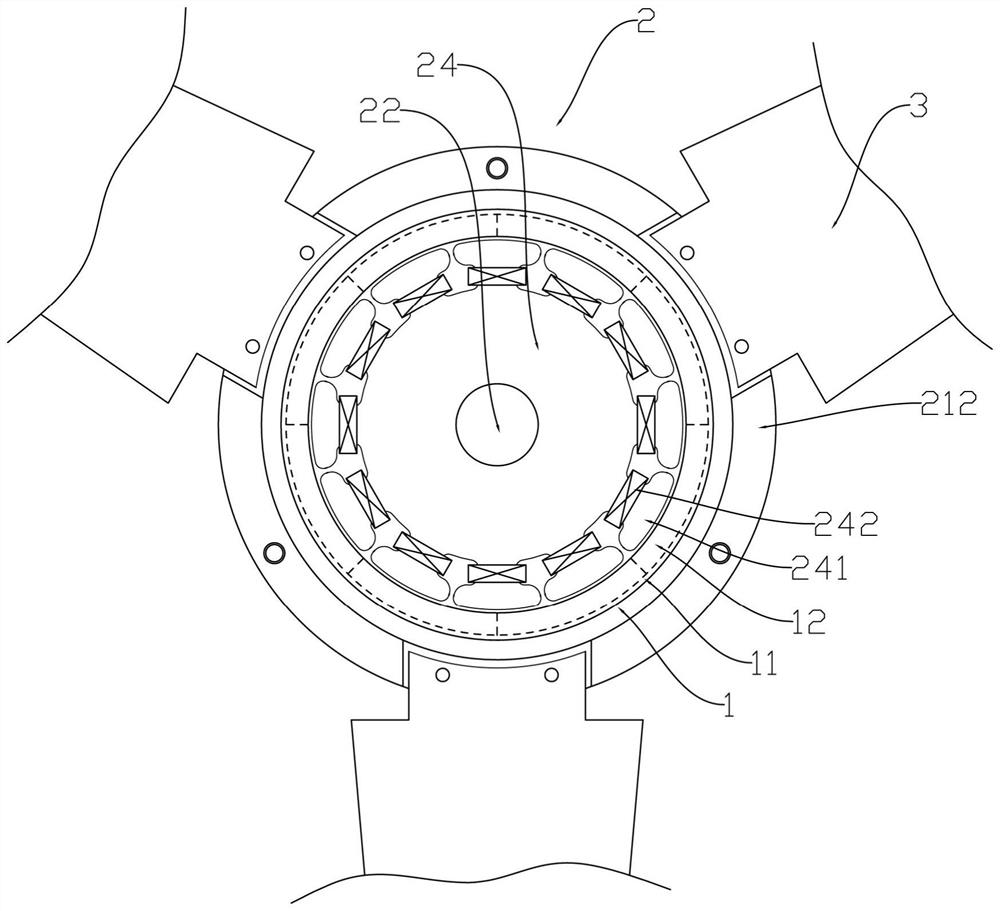
[0043] Such as figure 1 As shown, it is a permanent magnet ring 1 used in the DC outer rotor motor 2 in the embodiment of the present invention. The permanent magnet ring 1 is a circular columnar structure integrally formed by magnetic powder and adhesive. The permanent magnet ring 1 includes the same The magnetically permeable ring layer 11 on the outer side of the shaft, and the magnetic pole ring layer 12 on the coaxial inner ring side. The magnetic pole ring layer 12 is evenly provided with eight magnetic poles along the circumferential direction, and one of the adjacent magnetic poles is an N pole facing the axis, and the other is an S pole facing the axis. figure 1 The...


PUM


Abstract

The invention discloses a permanent magnet ring, a motor applying the permanent magnet ring, a manufacturing method and a mold, and belongs to the field of motor permanent magnet rotors. The permanent magnet ring is of a circular ring columnar structure integrally formed by magnetic powder and an adhesive, and comprises a magnetic conductive ring layer and a magnetic pole ring layer, wherein the magnetic pole ring layer is uniformly provided with a plurality of adjacent and opposite magnetic poles in the circumferential direction, and the magnetic conductive ring layer can enable the magnetic field of each magnetic pole to be restrained in the magnetic conductive ring layer. According to the permanent magnet ring, a magnetic conductive component of a motor can be omitted, and the permanent magnet ring can be directly assembled as a rotor of the motor, so that the step of installing the magnetic conductive ring on the magnetic ring during motor processing and assembling is omitted, and the process is greatly simplified; and the installation component of the permanent magnet ring in the motor is allowed to be made of a non-magnetic conductive material so as to expand the material selection possibility of the motor part, so that the use process possibility of the motor is further expanded, the cost of the motor is reduced, and the processing efficiency is improved.

Description

technical field [0001] The invention relates to the field of permanent magnet rotors of motors, in particular to a permanent magnet ring and its applied motor, a manufacturing method and a mold. Background technique [0002] Motor refers to an electromagnetic device that realizes the conversion or transmission of electric energy according to the law of magnetic induction. According to the type of power supply, motors are divided into DC motors and AC motors, and DC motors are further divided into brushless DC motors and brushed DC motors. Brushless DC motors use electronic commutation to replace traditional contact commutators and brushes. The DC motor can be subdivided into outer rotor and inner rotor permanent magnet motors, which use the magnetic field of the stator changing with time to force the fixed magnetic field of the rotor to generate rotational power, that is, to drive the permanent magnet ring to rotate and perform work. In addition to motors, permanent magnet...

Claims


Application Information

Patent Timeline
IPC IPC(8): H02K1/22H02K1/2789H02K1/02H02K5/02H02K5/04H02K15/03H01F41/02H01F13/00
CPCH02K1/22H02K1/2786H02K1/02H02K5/02H02K5/04H02K15/03H01F41/0266H01F13/00H01F13/003
Inventor 莫锦源梁文超林焕军
Owner 江门市邦特电子电器有限公司
Learn More