
A U-shaped layer twisted skeleton ribbon optical cable and its slot-in device

A ribbon-shaped optical cable and layer-twisted technology, which is applied in the field of optical communication transmission, can solve the problems of poor temperature performance of the ribbon optical cable of the skeleton, low manufacturing efficiency of the skeleton, and poor bending performance of the skeleton ribbon, so as to improve usability and applicability, and improve Effect of minimum bending radius and improvement of temperature performance

Active Publication Date: 2022-07-08
SHANTOU HIGH TECH ZONE AOXING OPTICAL COMM EQUIP +1
View PDF6 Cites 0 Cited by
  • Summary
  • Abstract
  • Description
  • Claims
  • Application Information

AI Technical Summary

Problems solved by technology

[0004] Aiming at the above defects or improvement needs of the prior art, the present invention provides a U-shaped layer stranded skeleton ribbon cable and its slotting device. , leading to the technical problem of low manufacturing efficiency of the skeleton, and when the optical fiber ribbon fixed in the skeleton groove is over-bent or over-stretched, the optical fiber ribbon will still be subjected to the side stress given by the skeleton, resulting in poor bending performance of the skeleton ribbon technical problems, and the technical problems of the poor temperature performance of the skeleton ribbon cable

Method used


Image

  • A U-shaped layer twisted skeleton ribbon optical cable and its slot-in device
  • A U-shaped layer twisted skeleton ribbon optical cable and its slot-in device
  • A U-shaped layer twisted skeleton ribbon optical cable and its slot-in device

Examples


Embodiment Construction

[0048] In order to make the objectives, technical solutions and advantages of the present invention clearer, the present invention will be further described in detail below with reference to the accompanying drawings and embodiments. It should be understood that the specific embodiments described herein are only used to explain the present invention, but not to limit the present invention. In addition, the technical features involved in the various embodiments of the present invention described below can be combined with each other as long as there is no conflict with each other.

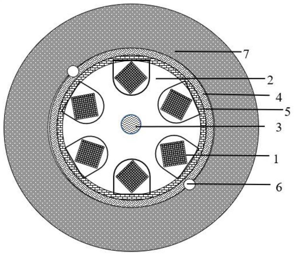
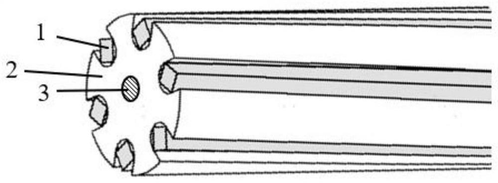
[0049] like figure 1 and figure 2 As shown, according to the first aspect of the present invention, there is provided a U-shaped layer twisted skeleton ribbon optical cable, which includes a reinforcing core 3, a skeleton 2, a water blocking tape 5, a fiber layer 4, and Sheath 7.

[0050]The reinforcing core 3 is disposed at the center of the frame 2 and penetrates the entire frame 2 along the a...


PUM


Abstract

The invention discloses a U-shaped layer twisted skeleton ribbon optical cable, comprising a reinforcing core, a skeleton, a fiber layer and a sheath arranged from the inside to the outside. It runs through the entire skeleton, the skeleton is a cylinder, and its outer edge is symmetrically provided with a plurality of U-shaped grooves, each U-shaped groove runs through the entire skeleton along the axial direction of the skeleton, and each U-shaped groove is provided with an optical fiber ribbon Matrix, in the radial direction of the skeleton, the optical fiber ribbon matrix includes P optical fiber ribbons arranged in parallel, and Q optical fibers are arranged horizontally in each optical fiber ribbon, where P is a natural number between 2 and 12, and Q is 4 to 24 A natural number between, in the axial direction of the skeleton, all P optical fiber ribbons in each U-shaped groove are twisted with each other in a unidirectional helical manner. The invention can solve the technical problem of low manufacturing efficiency of the skeleton due to the need to set the skeleton pay-off equipment in the existing skeleton ribbon optical cable.

Description

technical field [0001] The invention belongs to the technical field of optical communication transmission, and more particularly relates to a U-shaped layer twisted skeleton ribbon optical cable and a slot-in device thereof. Background technique [0002] The existing skeleton ribbon cable includes a unidirectional helical skeleton. The optical fiber ribbons are superimposed into a matrix form and embedded in the skeleton grooves. Optical fiber ribbons are characterized by consistent bending performance in all directions. [0003] However, the existing skeleton ribbon cable still has some deficiencies that cannot be ignored: first, the manufacturing efficiency of the skeleton is low due to the need to set the skeleton pay-off equipment; During the transitional stretching, the optical fiber ribbon will still be subjected to the lateral stress given by the skeleton, resulting in poor bending performance of the skeleton ribbon; third, the temperature performance of the skeleton...

Claims


Application Information

Patent Timeline
Patent Type & Authority Patents(China)
IPC IPC(8): G02B6/44
CPCG02B6/4403G02B6/443G02B6/4432G02B6/4429G02B6/4479G02B6/4486G02B6/449G02B6/4413G02B6/4411G02B6/44384
Inventor 马波杜家佳阎浩刘喆驰刘爱华
Owner SHANTOU HIGH TECH ZONE AOXING OPTICAL COMM EQUIP
Learn More