LED lamp supporting equipment for improving visibility in foggy days
A technology of LED lights and supporting equipment, which is applied in mechanical equipment, lighting and heating equipment, energy-saving lighting, etc., can solve the problems of poor fog penetration and discomfort of human eyes, and achieve the effect of improving visibility
- Summary
- Abstract
- Description
- Claims
- Application Information
AI Technical Summary
Problems solved by technology
Method used
Image
Examples
Embodiment 1
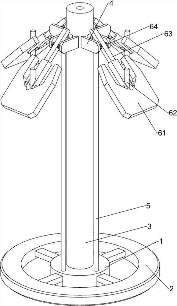
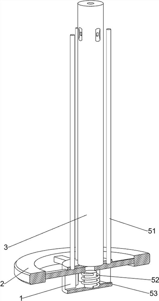
[0036] A kind of LED lamp supporting device for improving visibility in foggy days, such as Figure 1 to Figure 9 As shown, it includes a base 1, a pressing block 2, a supporting column 3, a first connecting plate 4, a supporting mechanism 5, a lighting mechanism 6, and a dispersing mechanism 7. The outer side of the base 1 is slidingly provided with a pressing block 2, and the top of the base 1 is provided with The support column 3, the support mechanism 5 is connected between the top of the pressing block 2 and the base 1, and four pairs of first connecting plates 4 are equidistantly arranged on the outside of the upper part of the supporting column 3, and the lighting mechanism 6 is connected between the first connecting plates 4. The top of the column 3 is provided with a dispersing mechanism 7 .
[0037] The support mechanism 5 includes a first connecting rod 51, a guide block 52 and a first spring 53. The bottom of the inner wall of the base 1 is provided with a guide bl...
Embodiment 2
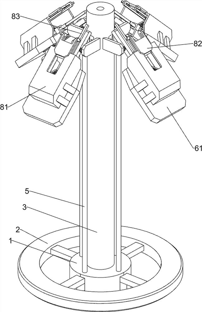
[0042] On the basis of Example 1, such as figure 1 , figure 2 , Figure 10 and Figure 11 As shown, it also includes a shielding mechanism 8. The shielding mechanism 8 includes a shielding frame 81, a baffle plate 82, a first push rod 83, a guide rod 84, a second spring 85, a solar panel 86, a second push rod 87, a first Guide frame 88 and the 3rd spring 89, place plate 61 tops are all provided with shielding frame 81, and shielding frame 81 tops are provided with guide rod 84 symmetrically sliding, are connected with baffle plate 82 between the guide rods 84 of same side, guide The second spring 85 is connected between the bottom of the rod 84 and the inner wall of the shielding frame 81, and the inner side of the top of the placement plate 61 is provided with a first guide frame 88, and the first guide frame 88 is slidably provided with a second push rod 87. The tops of the two push rods 87 are slidingly provided with the first push rod 83, the bottom of the first push r...
Embodiment 3
[0045] On the basis of Example 2, such as figure 1 , figure 2 , Figure 12 , Figure 13 , Figure 14 and Figure 15 As shown, it also includes a locking mechanism 9, and the locking mechanism 9 includes a second connecting plate 91, a third connecting rod 92, a rubber ring 93, a second guide frame 94, a block 95 and a fourth spring 96, and the supporting column 3. The bottom sliding type is provided with a second connecting plate 91, and the front, rear, left, and right sides of the bottom of the base 1 are all provided with a second guide frame 94, and the outside of the second guide frame 94 is slidingly provided with a block 95, and the inside of the block 95 is all slidable. A fourth spring 96 is connected between the inner wall of the second guide frame 94, a third connecting rod 92 is provided on the top of the block 95, and the top of the third connecting rod 92 is hook-shaped, and a rubber ring 93 is provided on the outside of the bottom of the support column 3 ....
PUM
 Abstract
Description
Claims
Application Information
 - Generate Ideas
- Intellectual Property
- Life Sciences
- Materials
- Tech Scout
- Unparalleled Data Quality
- Higher Quality Content
- 60% Fewer Hallucinations
Browse by: Latest US Patents, China's latest patents, Technical Efficacy Thesaurus, Application Domain, Technology Topic, Popular Technical Reports.
© 2025 PatSnap. All rights reserved.Legal|Privacy policy|Modern Slavery Act Transparency Statement|Sitemap|About US| Contact US: help@patsnap.com


