
Composite material injection molding method

A technology of injection molding and composite materials, applied in coating and other directions, which can solve problems such as cracking of ceramic shells

Pending Publication Date: 2022-01-18
GOERTEK INC
View PDF9 Cites 0 Cited by
  • Summary
  • Abstract
  • Description
  • Claims
  • Application Information

AI Technical Summary

Problems solved by technology

[0005] The main purpose of the present invention is to propose a composite material injection molding method, aiming to solve the technical problem that the ceramic shell cracks during the injection molding process of the existing nano-injection molding process

Method used


Image

  • Composite material injection molding method
  • Composite material injection molding method

Examples


Embodiment Construction

[0032] The technical solutions in the embodiments of the present invention will be clearly and completely described below in conjunction with the embodiments of the present invention. It should be understood that the specific embodiments described here are only used to explain the present invention, and are only part of the embodiments of the present invention. Not all examples. Based on the embodiments of the present invention, all other embodiments obtained by persons of ordinary skill in the art without creative efforts fall within the protection scope of the present invention.

[0033] In addition, the technical solutions of the various embodiments can be combined with each other, but it must be based on the realization of those skilled in the art. When the combination of technical solutions is contradictory or cannot be realized, it should be considered that the combination of technical solutions does not exist , nor within the scope of protection required by the present ...


PUM


Abstract

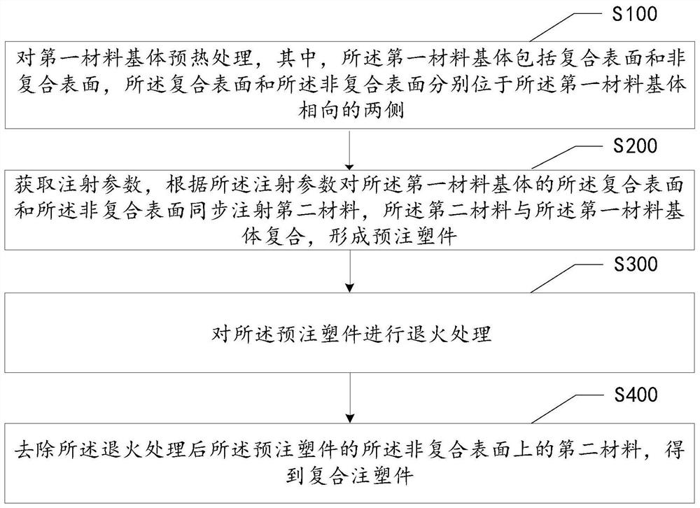
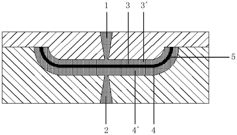
The invention discloses a composite material injection molding method. The composite material injection molding method comprises the following steps: preheating a first material matrix; obtaining injection parameters, and injecting a second material to a composite surface and a non-composite surface of the first material matrix synchronously according to the injection parameters, so that the second material is compounded with the first material matrix to form a pre-injection molded part; carrying out annealing treatment on the pre-injection molded part; and removing the second material on the non-composite surface of the pre-injection molded part subjected to annealing treatment, so that the composite injection-molded part is obtained. Compared with the prior art, the composite material injection molding method provided by the invention has the advantages that: the injection parameters are set, and the second material is simultaneously injected on the composite surface and the non-composite surface on the inner side and the outer side of the first material matrix according to the injection parameters, so that the pressure borne by the two sides of the first material matrix from the second material is always kept balanced; and therefore, the first material matrix is prevented from being broken in the injection molding process.

Description

technical field [0001] The invention relates to the field of material molding, in particular to a composite material injection molding method. Background technique [0002] In the 5G era, the network transmission rate has been greatly improved, but at the same time, due to the short wavelength of 5G electromagnetic waves, it is easy to be shielded, so 3C electronic products are more picky about the material of the shell. Due to metal's shielding of signals, traditional metal materials can no longer meet the transmission requirements of 5G signals, and materials with low shielding properties are undoubtedly a better choice. As an inorganic non-metallic material, ceramics have the characteristics of low shielding, high hardness and high wear resistance, and are ideal materials for making 3C electronic products. [0003] As a hard and brittle material, ceramics have high hardness and are extremely difficult to process. Therefore, ceramic nano-injection molding technology is u...

Claims


Application Information

Patent Timeline
IPC IPC(8): B29C45/14B29C45/16B29C45/27B29C45/77B29C45/72B29B13/02B29C45/17B29C71/02
CPCB29C45/1418B29C45/164B29C45/2708B29C45/1769B29C45/77B29C45/72B29B13/023B29C71/02B29C2045/14286B29C2071/022
Inventor 李文涛李忠军崔基国毛咏发毛桂江李扬樊凯
Owner GOERTEK INC
Learn More