Winding tool and application method thereof
A tooling and winding technology, applied in the field of tooling, can solve the problems that the stretching force of the suture cannot be accurately controlled, the stability of the product processing effect cannot be ensured, and the processing time is consumed, so as to shorten the straightening time and accurately control the stretching. Strength, the effect of increasing friction
- Summary
- Abstract
- Description
- Claims
- Application Information
AI Technical Summary
Problems solved by technology
Method used
Image
Examples
Embodiment 1
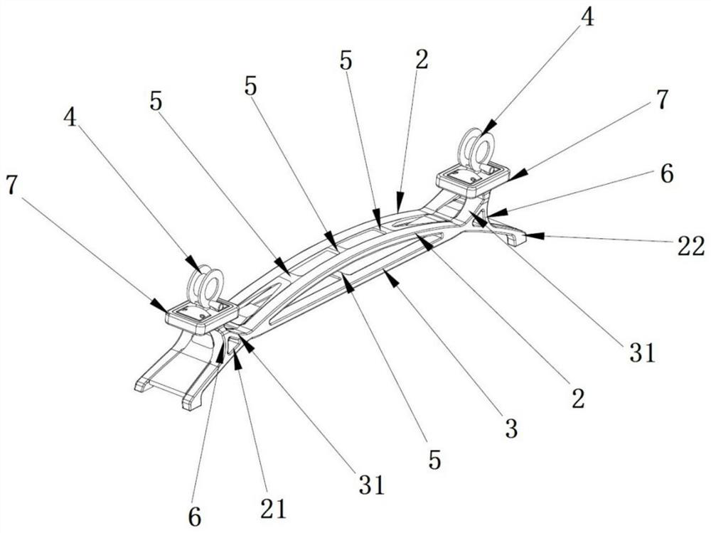
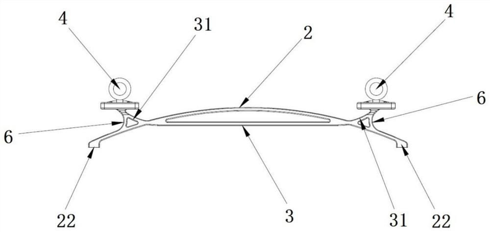
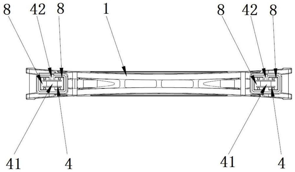
[0035] Such as figure 1 , image 3 As shown, the wire winding tool includes a bracket 1, and two wire winders 4 symmetrically arranged at both ends of the bracket 1, the wire winder 4 includes a rotatable central shaft 41, and the wire winder 4 A handle 42 that can rotate and fix the central axis 41 of the winding device 4 is provided on the top, and the rotation direction of the central axis 41 of the winding device 4 is the same as that of the handle 42. When the handle 42 is turned clockwise, the The central shaft 41 of the winder 4 rotates clockwise with the handle 42. When the handle 42 is turned counterclockwise, the central shaft 41 of the winder 4 rotates counterclockwise with the handle 42. When the handle 42 stops rotating, the winder 4 The central axis 41 is fixed in position and stops rotating. The support 1 is made of a highly rigid metal material. In other solutions, the support 1 can also be made of other materials with certain rigidity and toughness. The suppo...
Embodiment 2
[0041] The wire winding tool includes a base, and two wire winders 4 symmetrically arranged at both ends of the support 1, the wire winders 4 are fixed on the base through a wire winder fixing platform, and the specific details of the wire winder 4 The winding method and function are the same as in Embodiment 1. The bottom of the winding device 4 and the winding device fixing table can be integrally formed, and can also be fixed by means of screw connection, pin connection or interference fit. Specifically, the The two ends of the base are provided with installation grooves, the winding device fixing table is fixed in the installation grooves by screws or spools, the bottom of the base is equidistantly provided with feet, and the bottom of the base is provided with weight-reducing grooves. In order to reduce the overall weight of the base, in other solutions, the feet provided on the bottom of the base can also be removed, and rubber pads can be provided on the contact surface ...
Embodiment 3
[0043] The winding tool includes rollers and a wire winder 4 arranged at both ends of the support 1, the support 1 includes arch bridge-shaped main beams 2 arranged in parallel, and the bottom of the arch bridge-shaped main beams 2 is provided with a supporting beam 3, so Connecting beams 5 are respectively arranged between the arch bridge-shaped main beams 2 and the supporting beams 3. The arch bridge-shaped main beams 2 intersect with the supporting beams 3 and extend to the outside of the intersection point. The arc-shaped support beam is connected with the extension 21 of the arch bridge-shaped main beam through the arc-shaped support beam 6. Specifically, the structure of the support 1 part of the winding tool is consistent with the structure of the support 1 part of the embodiment 1. In the support One end of 1 is fixed with a wire winder 4, and the other end is fixed with a non-rotatable roller to replace the wire winder 4. The radius of the roller is consistent with the...
PUM
| Property | Measurement | Unit |
|---|---|---|
| Curved arc | aaaaa | aaaaa |
| Radian | aaaaa | aaaaa |
Abstract
Description
Claims
Application Information
 - R&D
- Intellectual Property
- Life Sciences
- Materials
- Tech Scout
- Unparalleled Data Quality
- Higher Quality Content
- 60% Fewer Hallucinations
Browse by: Latest US Patents, China's latest patents, Technical Efficacy Thesaurus, Application Domain, Technology Topic, Popular Technical Reports.
© 2025 PatSnap. All rights reserved.Legal|Privacy policy|Modern Slavery Act Transparency Statement|Sitemap|About US| Contact US: help@patsnap.com


