
High-voltage power transmission line detonating cord fixing device

A technology of high-voltage transmission lines and high-voltage transmission lines, which is applied in the installation of cables, overhead installations, electrical components, etc., can solve the problems of deicing failure, deformation of transmission towers, damage to power grids, etc., and achieves simple and practical installation and good mechanical reliability. , the effect of good plastic deformation

Active Publication Date: 2022-01-11
SHANDONG UNIV
View PDF6 Cites 0 Cited by
  • Summary
  • Abstract
  • Description
  • Claims
  • Application Information

AI Technical Summary

Problems solved by technology

[0003] In some rainy and snowy or humid suburban areas, rime, rime, and ice coating often appear on the distribution lines. If the rime, rime, and ice coating that have solidified on the line have accumulated It will continue to increase, and eventually the transmission line will be overstretched, the relevant circuit components will be worn out, and even the transmission tower will be deformed, unstable and collapsed, and the adjacent transmission tower will be continuously damaged, causing serious damage to the power grid and affecting the economic development of the power transmission place. , social operation and normal life have a major impact
[0004] However, such severe electrical accidents caused by transmission line consolidation are not inevitable
At present, in order to deal with the problem, two methods are generally used for deicing. The first method is that relevant personnel climb on the transmission tower to carry out high-altitude operations, and use deicing tools and corresponding protective measures to manually deicing. This method is the most direct, but During the deicing process, because the transmission lines and transmission towers will be covered with rain and snow, it is very easy to affect the reliability of the safety equipment in the manual deicing process, and it poses a severe test to the life safety of personnel working at heights, and this kind of The labor cost required by the method is relatively expensive; the second is to use some thermal deicing facilities such as thermal deicing vehicles, thermal deicing robots, etc., to use electric energy to generate heat to melt the ice and snow solidification on the transmission line, so that However, this method will be affected by factors such as terrain and icing length. Many large-scale thermal deicing facilities cannot be specifically applied because of the harsh geographical environment such as plateaus, hills or cliffs where overhead transmission lines are located. Moreover, some thermal deicing robots with good performance fail to deice because the internal battery energy storage is not enough to remove the solidification of long ice-coated lines, which wastes a lot of energy. It is not recommended to use them in the current environment of energy shortage.
[0005] At present, there is a method of blasting deicing, which overcomes the defects of the above two methods. It needs to use a fixing device to fix the detonating cord under the high-voltage transmission line. When the ice layer of the high-voltage transmission line reaches the set thickness, Using the detonation index blasting blasting device, using vibration to de-ice, but the inventor found that the current detonating cord fixing device cannot meet the use requirements of high-voltage transmission lines with different diameters, and the distance between the high-voltage transmission line and the detonating cord cannot be adjusted , unable to meet the blasting deicing requirements in complex environments

Method used


Image

  • High-voltage power transmission line detonating cord fixing device
  • High-voltage power transmission line detonating cord fixing device
  • High-voltage power transmission line detonating cord fixing device

Examples


Embodiment 1

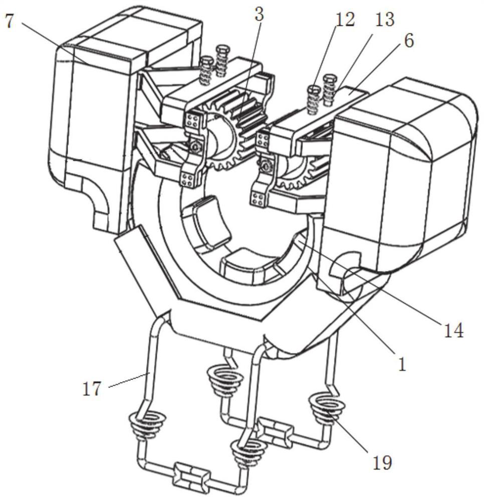
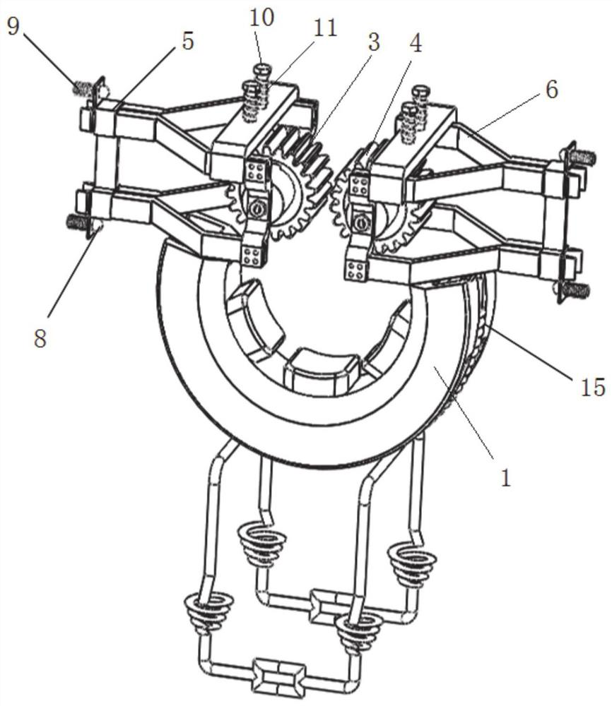
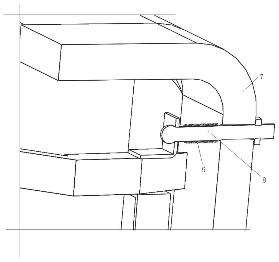
[0034] This embodiment provides a high-voltage transmission line detonating cord fixing device, such as Figure 1-Figure 6 As shown, it includes a fixing piece 1, which is used to lock and fix the high-voltage transmission line 2. In this embodiment, the fixing piece 1 adopts a ring-shaped shell structure with a gap on the top, which has a The space for accommodating the high-voltage transmission line 2 , the high-voltage transmission line 2 can enter the interior of the fixing piece 1 from the gap at the top of the fixing piece 1 , and then the fixing piece 1 and the high-voltage transmission line 2 are locked and fixed.

[0035] The first gear 3 and the second gear 4 used in pairs are arranged above the fixed part 1, the axes of the first gear 3 and the second gear 4 are arranged parallel to the axis of the fixed part 1, and the first gear 3 and the second gear The two gears 4 can move towards or away from each other.

[0036] The first gear 3 is rotatably connected to the ...


PUM


Abstract

The invention relates to a high-voltage power transmission line detonating cord fixing device which comprises a fixing part. The fixing part is provided with a space used for containing a high-voltage power transmission line, a first gear and a second gear which can move towards each other or away from each other are arranged above the fixing part, and the first gear is elastically connected with a shell through a first frame body; the second gear is elastically connected with the shell through a second frame body, the shell is fixed to the top of the fixing part, and the top of the first frame body is elastically connected with a first locking piece capable of being inserted between the adjacent gear teeth of the first gear; the top of the second frame body is elastically connected with a second locking piece capable of being inserted between the adjacent gear teeth of the second gear, and a detonating cord fixing element is arranged at the bottom of the fixing part. The fixing device provided by the invention meets the requirements of fixing the detonating cords below the high-voltage power transmission lines with different diameters.

Description

technical field [0001] The invention relates to the technical field of blasting and deicing of overhead power transmission lines, in particular to a detonating cord fixing device for high-voltage power transmission lines. Background technique [0002] The statements herein merely provide background information related to the present invention and do not necessarily constitute prior art. [0003] In some rainy and snowy or humid suburban areas, rime, rime, and ice coating often appear on the distribution lines. If the rime, rime, and ice coating that have solidified on the line have accumulated It will continue to increase, and eventually the transmission line will be overstretched, the relevant circuit components will be worn out, and even the transmission tower will be deformed, unstable and collapsed, and the adjacent transmission tower will be continuously damaged, causing serious damage to the power grid and affecting the economic development of the power transmission pl...

Claims


Application Information

Patent Timeline
Patent Type & Authority Applications(China)
IPC IPC(8): H02G7/16
CPCH02G7/16
Inventor 张建华卜杨胡向义赵赫
Owner SHANDONG UNIV
Learn More