
Test wafer, chip forming method and chip testing method

A technology for testing wafers and testing areas, applied in semiconductor/solid-state device testing/measurement, electronic circuit testing, electrical measurement, etc., can solve problems such as logic wafer scrapping, save packaging and testing costs, and reduce scrapping rates. Effect

Pending Publication Date: 2022-01-11
ICLEAGUE TECH CO LTD
View PDF0 Cites 0 Cited by
  • Summary
  • Abstract
  • Description
  • Claims
  • Application Information

AI Technical Summary

Problems solved by technology

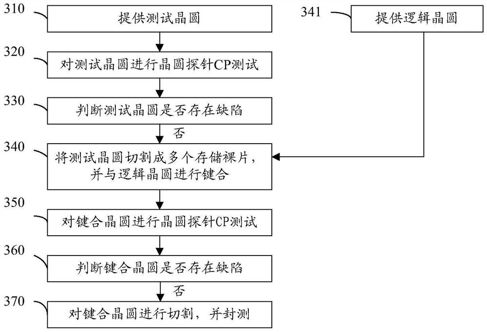
[0003] However, this type of probe detection can only be performed on wafers that have been bonded. Once there is a defect in the memory wafer in the bonded wafer, the logic wafer bonded to it will also be scrapped.

Method used

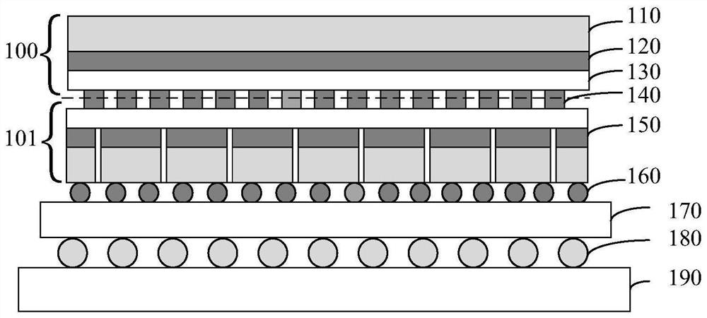

Image

  • Test wafer, chip forming method and chip testing method
  • Test wafer, chip forming method and chip testing method
  • Test wafer, chip forming method and chip testing method

Examples


Embodiment Construction

[0030] Exemplary embodiments disclosed in the present application will be described in more detail below with reference to the accompanying drawings. Although exemplary embodiments of the present application are shown in the drawings, it should be understood that the present application may be embodied in various forms and should not be limited to the specific embodiments set forth herein. Rather, these embodiments are provided for a more thorough understanding of the present application and for fully conveying the scope disclosed in the present application to those skilled in the art.

[0031] In the following description, numerous specific details are given in order to provide a more thorough understanding of the present application. It will be apparent, however, to one skilled in the art that the present application may be practiced without one or more of these details. In other examples, in order to avoid confusion with the present application, some technical features kno...


PUM


Abstract

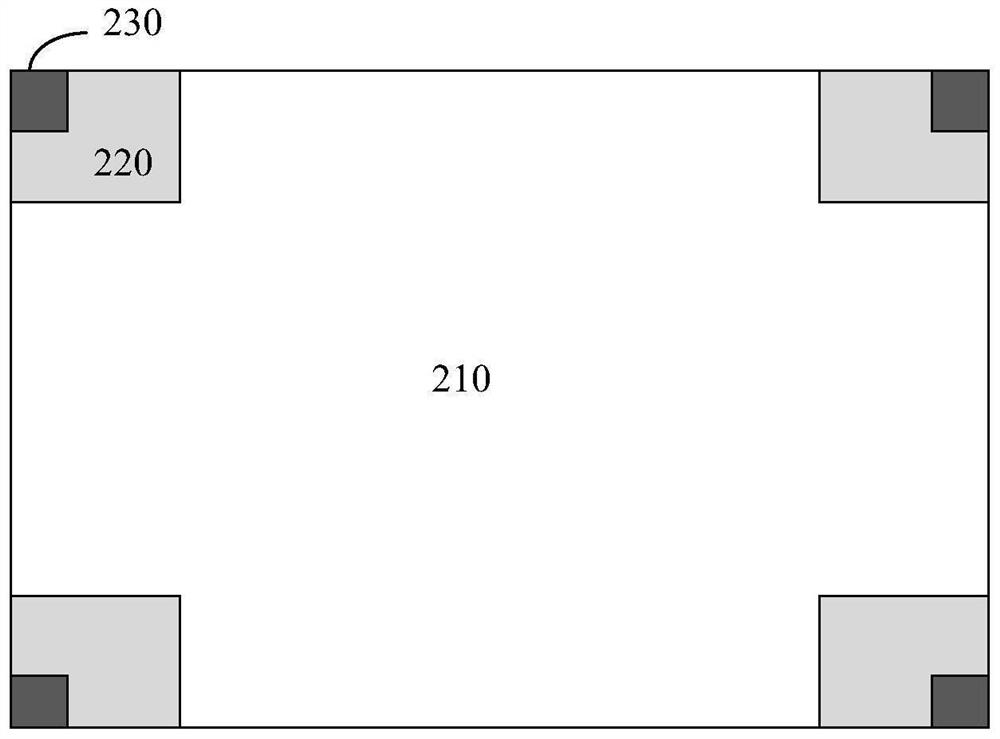
The invention discloses a test wafer, a chip forming method and a chip testing method. The test wafer comprises a plurality of storage bare chips, each storage bare chip is provided with a plurality of test areas, and each test area comprises a control logic area and a pad area which are electrically connected; the control logic area is electrically connected with the corresponding storage bare chip, and the control logic area is integrated with control logic of a logic bare chip; and the pad area is used for carrying out a wafer probe CP test.

Description

technical field [0001] The present application relates to the field of semiconductor technology, in particular to a test wafer, a method for forming a chip and a method for testing a chip. Background technique [0002] The manufacturing process of integrated circuits can usually be divided into wafer manufacturing process, wafer testing, packaging and final testing. Before chip packaging, it is usually necessary to conduct an electrical performance test on the integrated circuit on the wafer to determine whether the integrated circuit is good, and the integrated circuit after the packaging process must undergo another electrical performance test to screen out the defects caused by the packaging process. Defective products caused by poor performance further improve the yield of the final product. In the related art, a wafer tester with several probes is usually used, the probes of the wafer tester are contacted with the integrated circuits of the wafer, and test signals are ...

Claims


Application Information

Patent Timeline
Patent Type & Authority Applications(China)
IPC IPC(8): H01L25/18H01L21/66H01L21/98G01R31/28G01R1/067G11C29/04G11C29/08
CPCH01L25/18H01L22/32H01L22/14H01L22/12H01L22/20H01L25/50G01R31/2853G01R1/06711G11C29/04G11C29/08
Inventor 王贻源
Owner ICLEAGUE TECH CO LTD
Learn More