
Chip testing method, chip testing equipment and chip

A chip testing, chip technology, applied in the direction of electronic circuit testing, measuring electricity, measuring devices, etc., can solve the problems of reducing the number of chips, reducing the testing efficiency of testing equipment, etc., and achieve the effect of saving I/O interfaces

Active Publication Date: 2021-09-24
CHANGXIN MEMORY TECH INC
View PDF6 Cites 0 Cited by
  • Summary
  • Abstract
  • Description
  • Claims
  • Application Information

AI Technical Summary

Problems solved by technology

When the available I / O interface of the test equipment is limited, occupying the I / O interface to configure the chip select line will reduce the test efficiency of the test equipment, reduce the number of chips that the test equipment can test, and make the number of tested chips limited by the test equipment I / O. Limitation on the number of O interfaces

Method used


Image

  • Chip testing method, chip testing equipment and chip
  • Chip testing method, chip testing equipment and chip
  • Chip testing method, chip testing equipment and chip

Examples


Embodiment Construction

[0075] Example embodiments will now be described more fully with reference to the accompanying drawings. Example embodiments may, however, be embodied in many forms and should not be construed as limited to the examples set forth herein; rather, these embodiments are provided so that this disclosure will be thorough and complete and will fully convey the concept of example embodiments to those skilled in the art. The described features, structures, or characteristics may be combined in any suitable manner in one or more embodiments. In the following description, numerous specific details are provided in order to give a thorough understanding of embodiments of the present disclosure. However, those skilled in the art will appreciate that the technical solutions of the present disclosure may be practiced without one or more of the specific details being omitted, or other methods, components, devices, steps, etc. may be adopted. In other instances, well-known technical solution...


PUM


Abstract

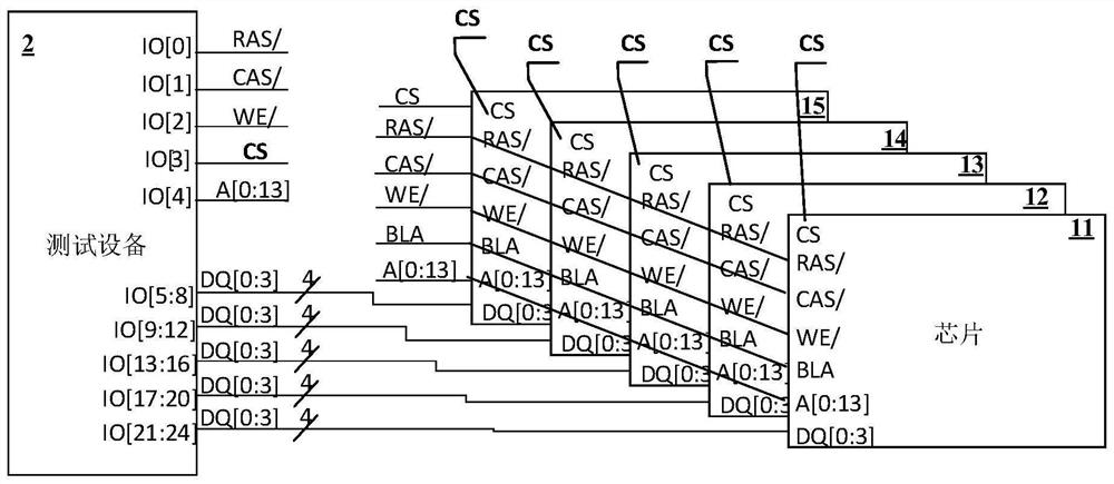
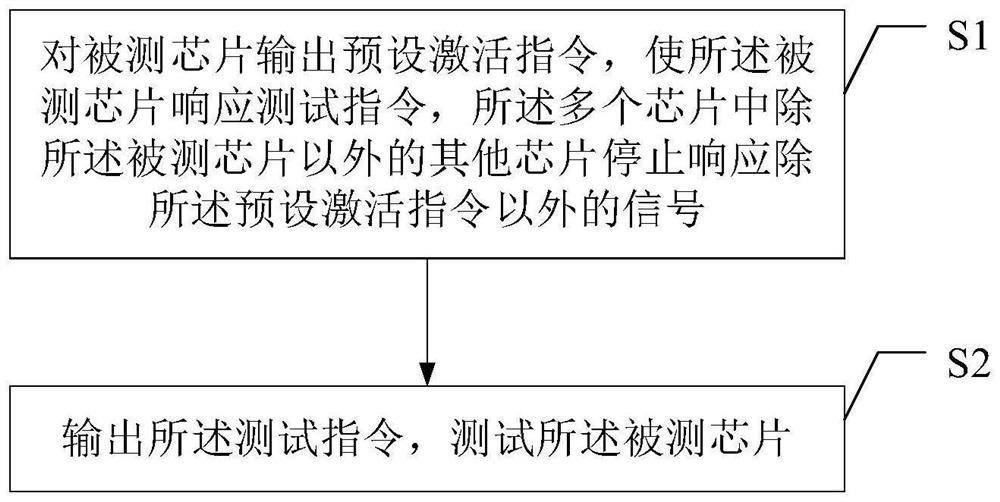
The disclosure provides a chip testing method, chip testing equipment and chips for testing multiple chips, and relates to the technical field of semiconductor testing. The chip testing method includes: outputting a preset activation command to the chip under test, so that the chip under test responds to the test command, and other chips in the plurality of chips except the chip under test stop responding to the preset activation command Signals other than; outputting the test instruction to test the chip under test. The chip testing method provided by the present disclosure can test as many chips as possible by utilizing limited test signal lines, and can realize individual testing of each chip.

Description

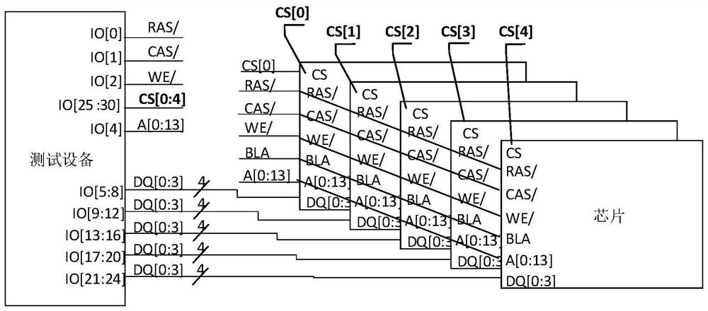
technical field [0001] The present disclosure relates to the technical field of semiconductor testing, and in particular, to a chip testing method, chip testing equipment and chips. Background technique [0002] In the related art, when testing multiple chips, in order to realize the individual testing of each chip, it is often necessary to configure a chip selection line for each chip separately. [0003] figure 1 It is a schematic diagram of a multi-chip test scenario in a related art. refer to figure 1 ,exist figure 1 Among them, the chip select lines of the five tested chips each occupy an I / O interface. When the available I / O interface of the test equipment is limited, occupying the I / O interface to configure the chip select line will reduce the test efficiency of the test equipment, reduce the number of chips that the test equipment can test, and make the number of tested chips limited by the test equipment I / O. Limitation on the number of O interfaces. [0004] ...

Claims


Application Information

Patent Timeline
Patent Type & Authority Patents(China)
IPC IPC(8): G01R31/28
CPCG01R31/2851G01R31/2886
Inventor 不公告发明人
Owner CHANGXIN MEMORY TECH INC
Learn More