Access control face recognizer for smart park center management
A technology for access control person and face recognition, which is applied in the field of access control face recognition devices, can solve problems such as infection, and achieve the effect of avoiding infection and recognition failure
- Summary
- Abstract
- Description
- Claims
- Application Information
AI Technical Summary
Problems solved by technology
Method used
Image

Examples
Embodiment 1
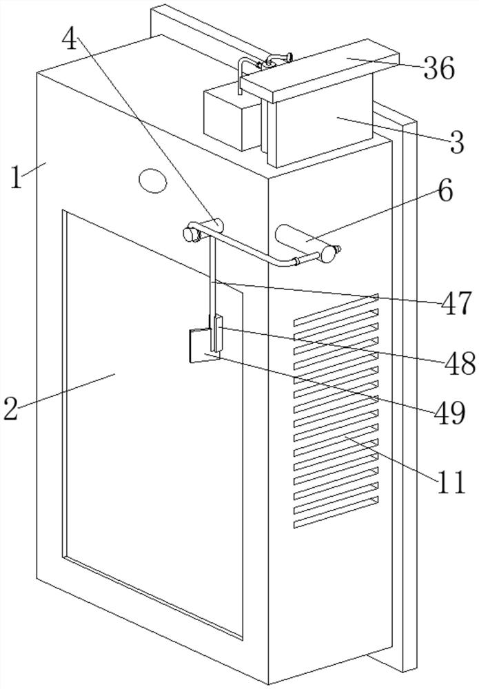
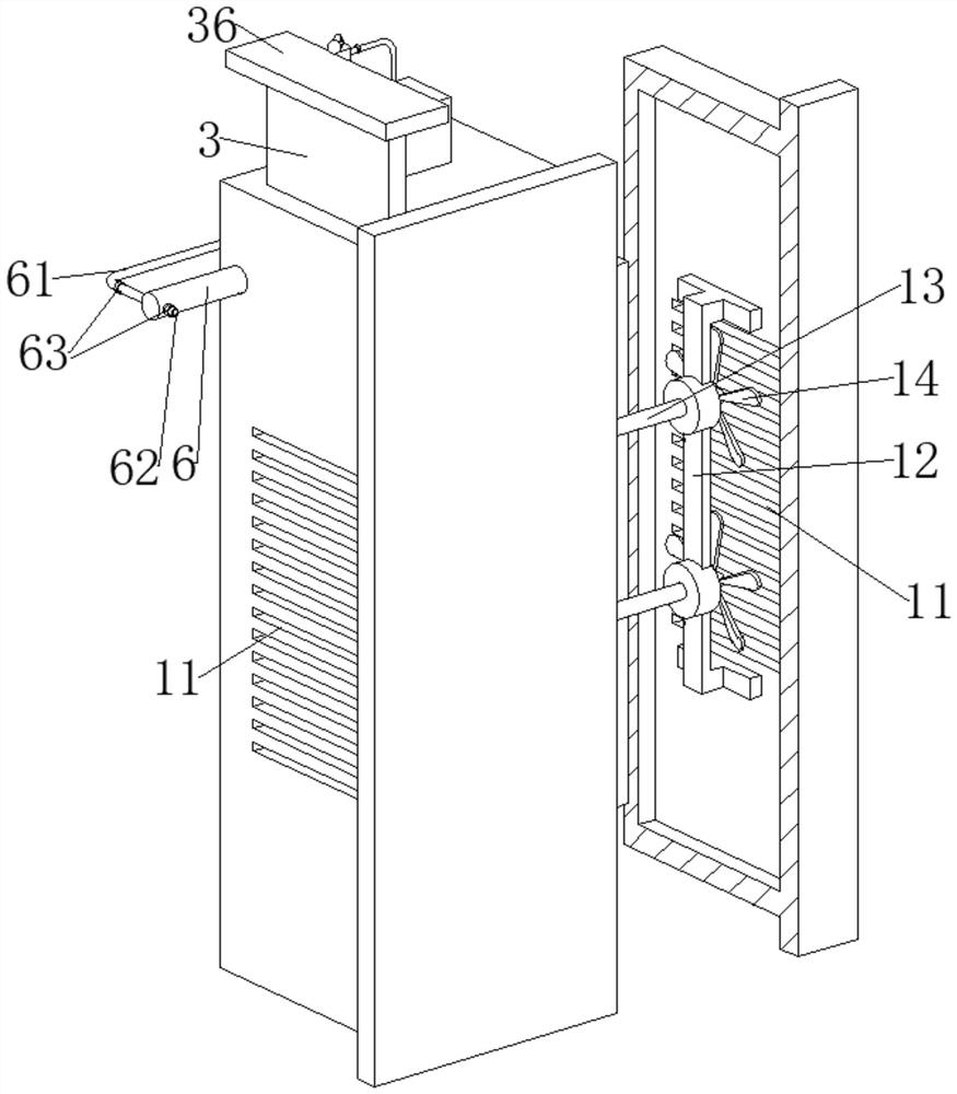
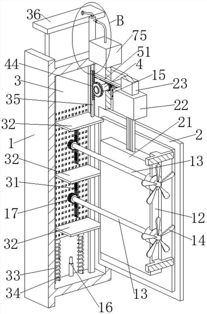
[0026] The present invention provides a technical solution: an access control face recognition device managed by the center of a smart park, including an installation shell 1, a display screen 2 is fixedly connected to the installation shell 1, a circuit board 21 is fixedly connected to the display screen 2, and the circuit board 21 is electrically connected to a camera 22, and a connection block 23 is fixedly connected to the camera 22. The connection block 23 is fixedly connected to the installation shell 1, and the installation shell 1 is slidably connected to the net box 3 with a built-in desiccant. The top of the net box 3 Fixedly connected with a press plate 36, the bottom of the net box 3 is fixedly connected with a first telescopic rod 33, the bottom of the first telescopic rod 33 is fixedly connected with the installation shell 1, the first telescopic rod 33 is sleeved with a first spring 34, The two ends of the first spring 34 respectively offset against the net box 3...
Embodiment 2
[0033] On the basis of Embodiment 1, furthermore, the installation shell 1 is provided with a cleaning mechanism for cleaning the dust on the camera 22, the cleaning mechanism includes a rotating rod 4, and a first one-way bearing 43 is fixedly connected to the rotating rod 4, And the rotating rod 4 is unidirectionally connected to the installation shell 1 through the first one-way bearing 43, the second one-way bearing 44 is fixedly connected on the rotating rod 4, and the second gear 41 is fixedly connected on the second one-way bearing 44, The second gear 41 meshes with the first rack 35 .
[0034] refer to image 3 , Figure 5 and Image 6 , because the first rack 35 meshes with the second gear 41, and then the first rack 35 can drive the second gear 41 to rotate back and forth when the first rack 35 follows the net box 3 and slides up and down. Image 6 As shown, when the first rack 35 slides down, it can drive the second gear 41 to rotate clockwise. At this time, the ...
Embodiment 3
[0038] On the basis of Embodiment 2, furthermore, the cleaning mechanism is provided with a wiping mechanism for wiping the position of the corresponding camera 22 on the housing, the wiping mechanism includes a pipeline 47 fixedly connected to the rotating rod 4, and the pipeline 47 is fixedly connected with The wiping block 48 is intermittently attached to the installation shell 1. The wiping mechanism also includes a second piston barrel 6 fixedly connected to the installation shell 1. A piston plate 511 is fixedly connected to the third rack 51, and the piston plate 511 slides Connected in the second piston barrel 6, the second piston barrel 6 is fixedly connected with an air inlet pipe 62 and an air outlet pipe 61, the air inlet pipe 62 and the air outlet pipe 61 are all provided with a second one-way valve 63, and the air outlet pipe 61 is far away from the first One end of the two piston barrels 6 is fixedly connected with a cylinder 45, and the cylinder 45 is rotatably ...
PUM
 Abstract
Description
Claims
Application Information
 - Generate Ideas
- Intellectual Property
- Life Sciences
- Materials
- Tech Scout
- Unparalleled Data Quality
- Higher Quality Content
- 60% Fewer Hallucinations
Browse by: Latest US Patents, China's latest patents, Technical Efficacy Thesaurus, Application Domain, Technology Topic, Popular Technical Reports.
© 2025 PatSnap. All rights reserved.Legal|Privacy policy|Modern Slavery Act Transparency Statement|Sitemap|About US| Contact US: help@patsnap.com