
Single-use lancet device

a single-use, lancet technology, applied in the field of single-use lancet devices, can solve the problems of sanitary problems, inconvenient assembly, and inability to use, and achieve the effect of improving the assembly efficiency reducing the number of components of the single-use lancet devi

Inactive Publication Date: 2007-04-05
KIM YONG PIL
View PDF6 Cites 72 Cited by
  • Summary
  • Abstract
  • Description
  • Claims
  • Application Information

AI Technical Summary

Benefits of technology

[0007] Therefore, the present invention has been made in view of the above problems, and it is an object of the present invention to provide a single-use lancet device wherein a lancet is not retracted once the lancet is shot such that reuse of the single-use lancet is prevented, the number of components constituting the single-use lancet device is decreased, and the assembly efficiency of the single-use lancet device is improved.
[0009] Preferably, the main body is provided at the inner circumferential surface of the front part thereof with protrusions, which are protruded to a predetermined height while being parallel with each other, and the wing plate and the stopping protrusion are provided at predetermined positions thereof with flat surface parts, which are diametrically opposite to each other, the flat surface parts of the wing plate and the stopping protrusion corresponding to the protrusions of the main body. Consequently, rotation of the actuating member in the main body is effectively prevented.
[0011] Preferably, the main body is provided at the outside thereof with a disc-shaped grip part, which is protruded along the outer circumferential surface of the main body. Consequently, manipulation of the single-use lancet device is easy and convenient.

Problems solved by technology

When the used lancet device is reused, however, sanitary problems, such as contagion, may occur, since the used lancet is stained with blood.
However, the structure of the single-use lancet device is complicated, and the number of components constituting the single-use lancet device is great.
Consequently, the manufacturing costs of the single-use lancet device are increased.

Method used


Image

  • Single-use lancet device
  • Single-use lancet device
  • Single-use lancet device

Examples


Embodiment Construction

[0022] Now, a preferred embodiment of the present invention will be described in detail with reference to the accompanying drawings.

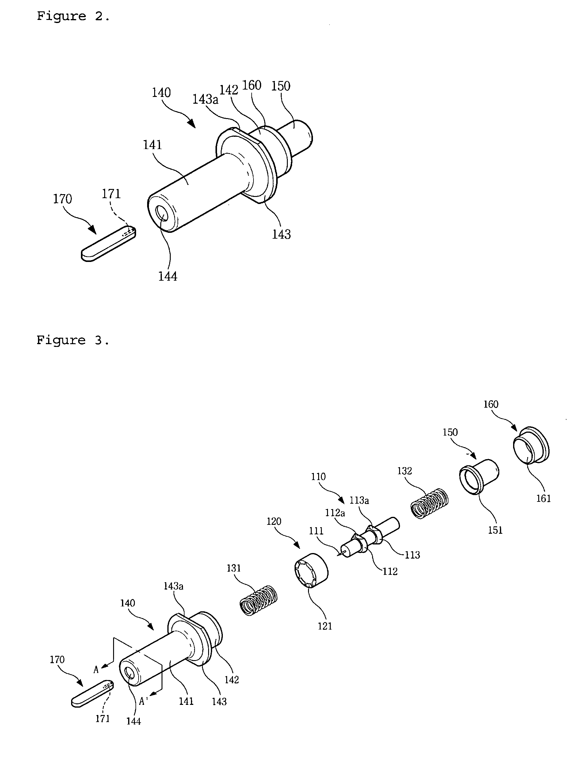
[0023]FIG. 2 is a perspective view illustrating a single-use lancet device according to the present invention. As shown in FIG. 2, an upper case 160 is coupled with the rear end of a main body 140, and a push member 150 is inserted through a circular hole 161 (see FIG. 3) formed at the upper case 160. The main body 140 is formed in the shape of a hollow cylinder, in which components of the lancet device are disposed. The main body 140 comprises a front main body 141, a rear main body 142, and a grip part 143. The diameter of the rear main body 142 is greater than that of the front main body 141. The main body 140 is manufactured such that the main body 140 has a predetermined thickness. For this reason, a fixing end 145 (see FIG. 5A) having a relatively small front-side inner diameter is formed at the boundary between the front main body 141 and the re...


PUM


Abstract

A single-use lancet device comprises a main body having a shooting hole and a fixing end, a first elastic member inserted in the main body, a wing plate catching member disposed in the main body while being caught by the fixing end and having a plurality of catching protrusions formed at the front end thereof, an actuating member disposed at the rear of the wing plate catching member such that a lancet is fixed to the front end of the actuating member, the actuating member having a wing plate and a stopping protrusion, the diameters of which are gradually decreased from the rear ends to the front ends of the wing plate and the stopping protrusion, the wing plate being caught by the catching protrusions, a second elastic member disposed at the rear of the actuating member, and a push member disposed at the rear part of the main body for applying pressure to the actuating member through the second elastic member when a user pushes the push member forward.

Description

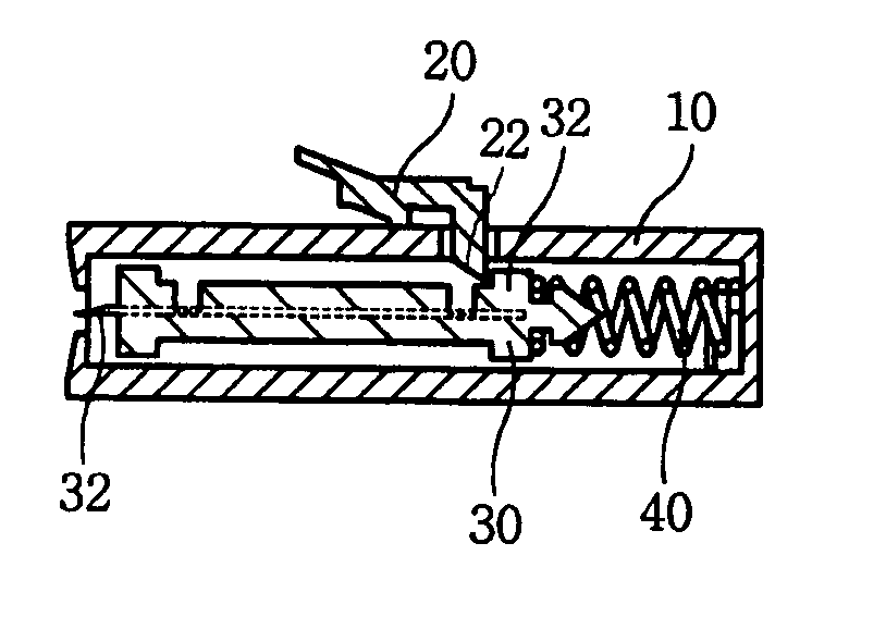
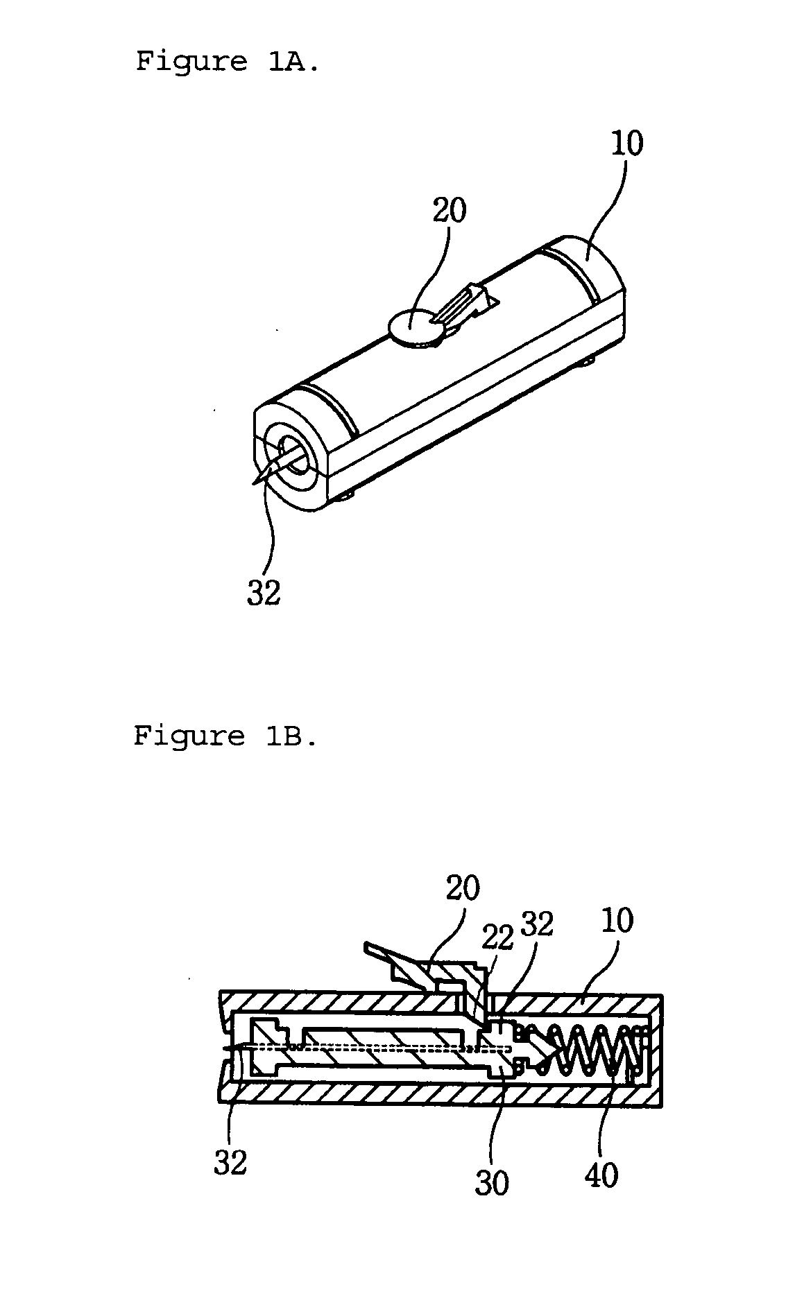
BACKGROUND OF THE INVENTION [0001] 1. Field of the Invention [0002] The present invention relates to a lancet device used to collect blood from a human body for the purpose of medical treatment, and, more particularly, to a single-use lancet device wherein reuse of the single-use lancet is prevented, the number of components constituting the single-use lancet device is decreased, and the assembly efficiency of the single-use lancet device is improved. [0003] 2. Description of the Related Art [0004] Generally, blood is collected, as occasion demands, to execute health examinations or treat patients. When a large amount of blood is needed, a syringe is used to collect the blood. When a small amount of blood is needed, for example, when the sugar content contained in blood of a diabetic is examined or a blood type test is performed, on the other hand, a lancet device is used to collect the blood. [0005]FIG. 1A is a perspective view illustrating a conventional single-use lancet device, ...

Claims


Application Information

Patent Timeline
IPC IPC(8): A61B17/32
CPCA61B5/1411A61B5/15142A61B5/150022A61B5/150412A61B5/150519A61B5/150549A61B5/150618A61B5/150717A61B5/150916A61B5/15111A61B5/15117A61B5/15144
Inventor KIM, YONG PIL
Owner KIM YONG PIL
Learn More