Test device and method for gas turbine lower transmission case test
A technology of gas turbine and test device, which is applied in gas turbine engine test, machine gear/transmission mechanism test, jet engine test, etc., can solve the problem of high test cost, high fuel cost, operation and maintenance cost, difficult direct parameter measurement of sensors, etc. problem, to achieve the effect of convenient operation and compact structure
Pending Publication Date: 2022-01-11
中国船舶重工集团公司第七〇三研究所无锡分部
View PDF4 Cites 0 Cited by
- Summary
- Abstract
- Description
- Claims
- Application Information
AI Technical Summary
Problems solved by technology
The actual operation of the lower transmission box suspended on the gas turbine is affected by the installation method, and it is difficult for the sensor to directly me
Method used
View moreImage
Smart ImageViewing Examples

Examples
 PUM
 Abstract
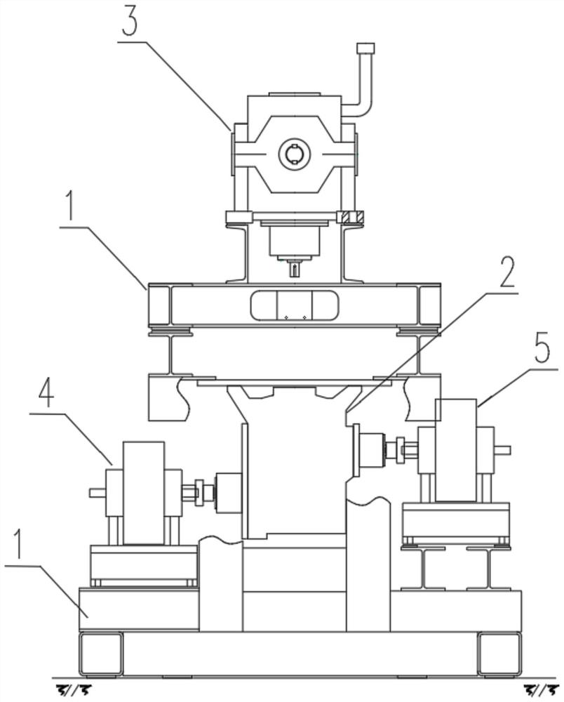
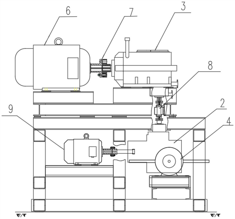
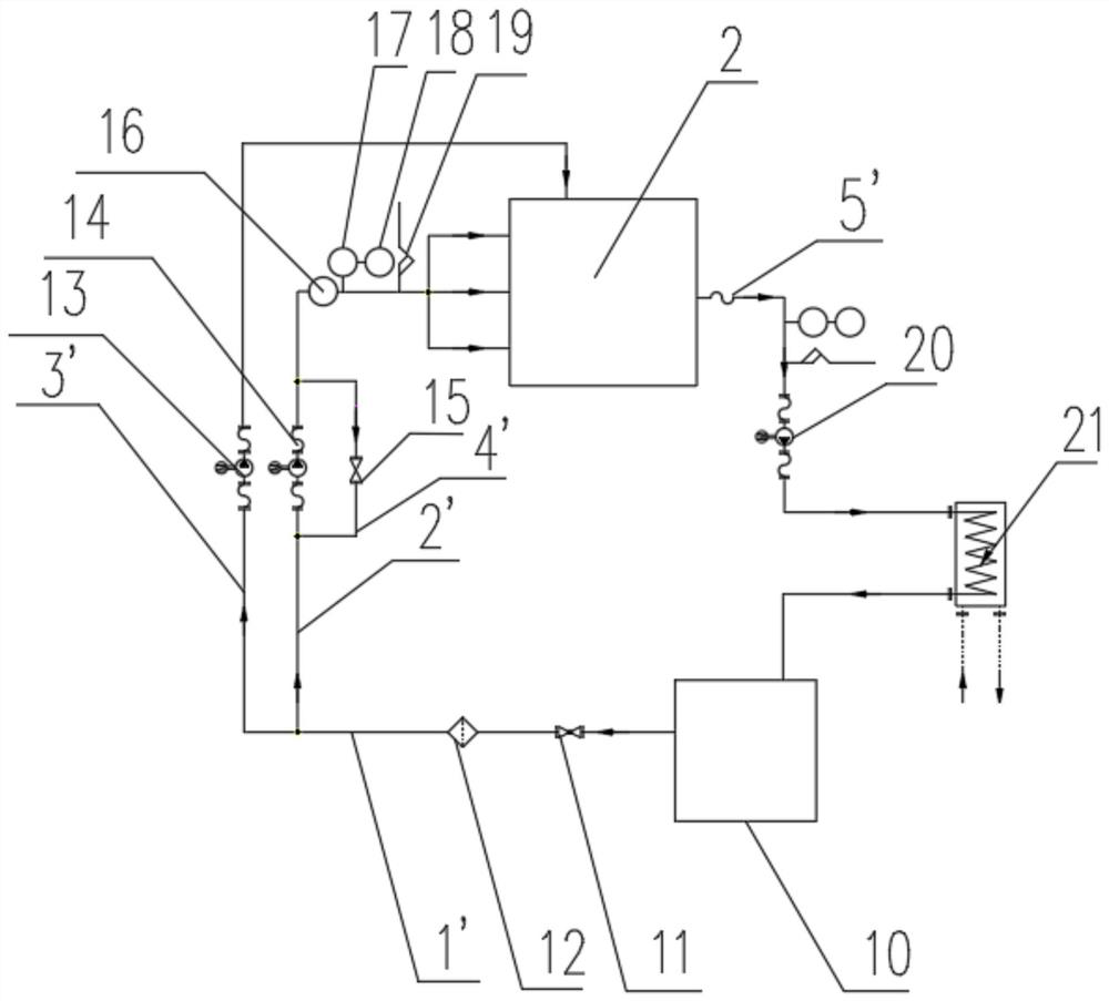
The invention relates to a method and a device suitable for testing a lower transmission case of a gas turbine. The device ensures that an installation mode, loads on the two sides and a driven mode of the lower transmission case are basically the same as an operation state of the lower transmission case on the gas turbine. The test device comprises an underframe, a step-up gear box, a main variable frequency motor, an auxiliary variable frequency motor, an eddy current dynamometer, a lubricating oil system, a measurement and control system and an electrical system. The test method comprises the steps of: the auxiliary variable frequency motor directly drives the lower transmission case to work in the starting stage; in the operation stage, the main variable frequency motor indirectly drives the lower transmission box through using the step-up gear box; the loads on the two sides of the lower transmission case are eddy current dynamometers and are used for simulating a fuel pump and a lubricating oil pump on the original two sides; the measurement and control system and the electrical system control, monitor, record and display the test. According to the test device, transmission efficiency measurement and reliability long-term test of the lower transmission case can be satisfied, and the device further has the advantages of high automation degree and low manpower and material resource investment.
Description
technical field [0001] The invention relates to the technical field of gas turbine lower transmission test, in particular to a test device and method for a gas turbine lower transmission case test. Background technique [0002] The lower transmission box of the gas turbine is an important transmission equipment of the gas turbine. Its basic working principle is as follows: during the start-up phase of the gas turbine, the auxiliary starter motor passes through the lower transmission box to drag and turn the compressor for ignition operation; One part is used for external work, and the other part is used for self-circulation to drive the compressor to rotate. During the running process, the lower transmission box has two important functions: one is to transmit the torque input by the auxiliary starter motor to the rotor of the gas turbine compressor for starting operation; the other is to transfer the auxiliary starter motor and the gas turbine compressor The torque is outpu...
Claims
Login to View More Application Information
Patent Timeline
 IPC IPC(8): G01M13/02G01M15/14
CPCG01M13/02G01M15/14
Inventor 吴一鸣贾新旺唐祖定俞希学张波
Owner 中国船舶重工集团公司第七〇三研究所无锡分部
Features
- Generate Ideas
- Intellectual Property
- Life Sciences
- Materials
- Tech Scout
- Unparalleled Data Quality
- Higher Quality Content
- 60% Fewer Hallucinations
Learn More Browse by: Latest US Patents, China's latest patents, Technical Efficacy Thesaurus, Application Domain, Technology Topic, Popular Technical Reports.
© 2025 PatSnap. All rights reserved.Legal|Privacy policy|Modern Slavery Act Transparency Statement|Sitemap|About US| Contact US: help@patsnap.com