


Quick Research
Generate reliable direction feasibility study reports for your R&D in just a few steps.

Technical Q&A
Discover and master advanced knowledge NOW. Basics, ideas, possibilities, all at once.

Find Solutions
As an expert in R&D theories, this can generate solutions to your technical problems instantly.

Evaluate Feasibility
Analyze your overall solution with one click, know your potential R&D risks in advance.

Monitor Landscape
Get weekly tech updates, stay abreast of the latest tech innovations and key insights.
Pipeline inspection robot
A technology for inspection robots and pipelines, which is applied to special pipes, pipe components, mechanical equipment, etc., can solve the problems of occupied space and large limitations, and achieve the effect of small space occupation, small limitations, and improved structural firmness
- Summary
- Abstract
- Description
- Claims
- Application Information
AI Technical Summary
Problems solved by technology
Method used
Image

Examples
Embodiment 1
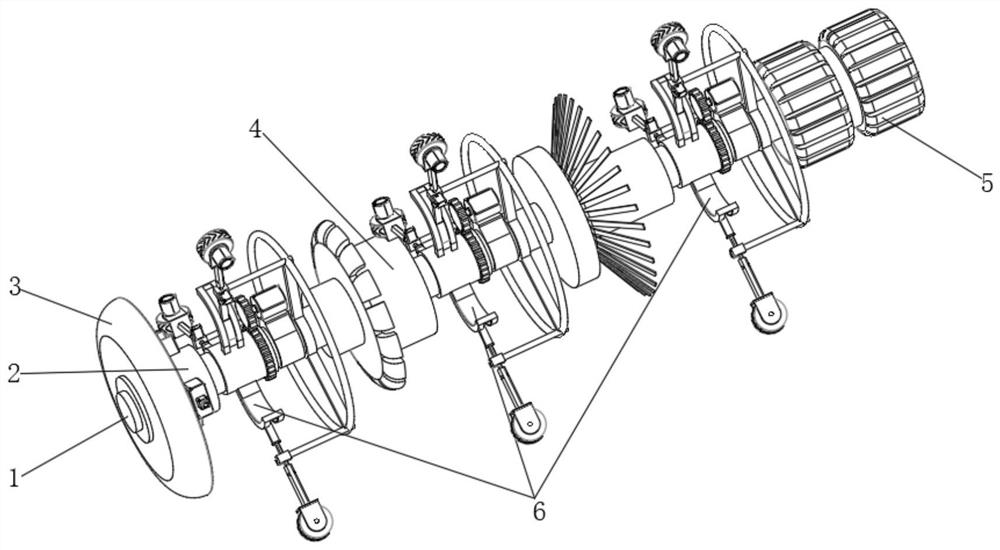
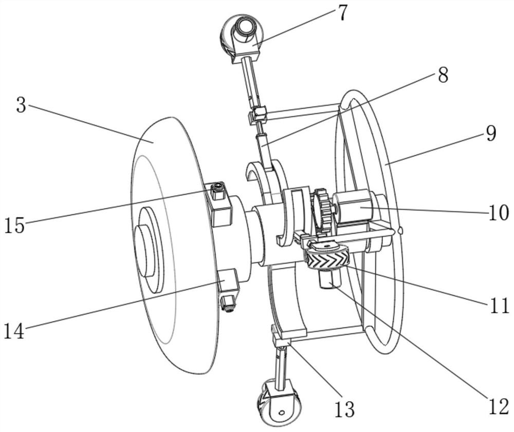
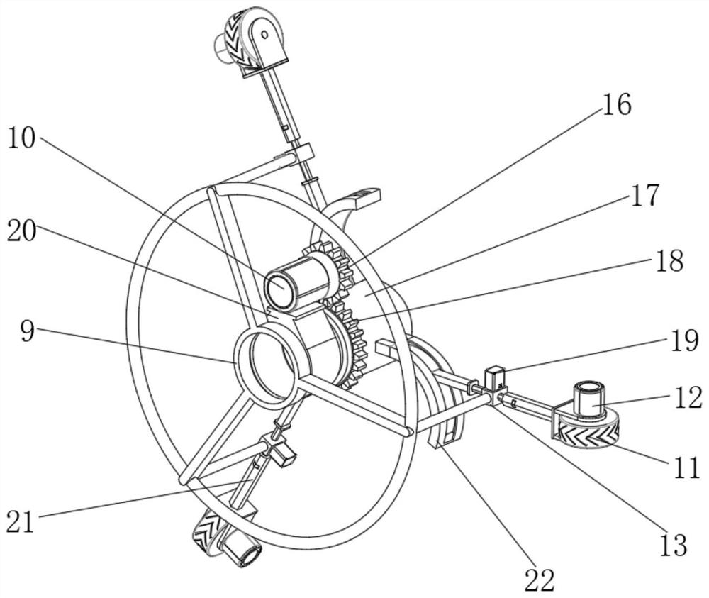
[0032] A pipeline inspection robot, such as Figure 1-4As shown, the first cylindrical body 1 is included, and the first driving mechanism 6 is installed on the first cylindrical body 1. The number of the first driving mechanisms 6 can be three or more. In this embodiment, preferably Yes, the number of the first driving mechanism 6 is three, the first driving mechanism 6 includes a mounting frame 9 and an adjusting motor 10, the adjusting motor 10 is installed on the outer wall of the first cylindrical body 1 through a connecting rod 20, and the mounting frame 9 is fixed on the peripheral outer wall of the first cylindrical main body 1, the output end of the adjustment motor 10 is rotatably connected to a driving gear 16, and the outer wall of the first cylindrical main body 1 is rotatably connected to a rotating seat 17, and the peripheral outer wall of the rotating seat 17 is integrally arranged There are driven teeth 18, and the driven teeth 18 are meshed with the driving g...
Embodiment 2
[0041] A pipeline inspection robot, such as Figure 5 , Figure 6 As shown, in order to be able to clean the inner wall of the pipeline; this embodiment makes the following improvements on the basis of Embodiment 1: the pipeline inspection robot also includes a cleaning tractor, and the cleaning tractor includes a second cylindrical main body 31 and The second driving mechanism 30 installed on the second cylindrical body 31, the number of the second driving mechanism 30 can be three or more, in this embodiment, preferably, the number of the second driving mechanism 30 is Three, the structure of the second driving mechanism 30 is the same as that of the first driving mechanism 6, and a With the same traction rope 32, the head end of the second cylindrical body 31 is equipped with a cleaning mechanism; by setting a cleaning tractor, the cleaning tractor can be made to enter the interior of the pipeline first, and the cleaning mechanism can be used to clean the pipeline and disc...
PUM
 Abstract
Description
Claims
Application Information
 - R&D Engineer
- R&D Manager
- IP Professional
- Industry Leading Data Capabilities
- Powerful AI technology
- Patent DNA Extraction
Browse by: Latest US Patents, China's latest patents, Technical Efficacy Thesaurus, Application Domain, Technology Topic, Popular Technical Reports.
© 2024 PatSnap. All rights reserved.Legal|Privacy policy|Modern Slavery Act Transparency Statement|Sitemap|About US| Contact US: help@patsnap.com