
Electromagnetic valve assembly control device and method

A technology of solenoid valve assembly and control device, applied in valve device, valve operation/release device, valve details, etc., can solve problems such as driver's driving risk, and achieve the effect of improving safety performance

Active Publication Date: 2022-01-11
宁波赛福汽车制动有限公司
View PDF7 Cites 0 Cited by
  • Summary
  • Abstract
  • Description
  • Claims
  • Application Information

AI Technical Summary

Problems solved by technology

[0005] The purpose of this application is to provide a solenoid valve assembly control device to solve the problem that the driver may have a driving risk when the MCU is down in the prior art

Method used


Image

  • Electromagnetic valve assembly control device and method
  • Electromagnetic valve assembly control device and method
  • Electromagnetic valve assembly control device and method

Examples


Embodiment Construction

[0047] In order to make the purposes, technical solutions and advantages of the embodiments of the present application clearer, the technical solutions in the embodiments of the present application will be clearly and completely described below in conjunction with the drawings in the embodiments of the present application. Obviously, the described embodiments It is a part of the embodiments of this application, not all of them. The components of the embodiments of the application generally described and illustrated in the figures herein may be arranged and designed in a variety of different configurations.

[0048] Accordingly, the following detailed description of the embodiments of the application provided in the accompanying drawings is not intended to limit the scope of the claimed application, but merely represents selected embodiments of the application. Based on the embodiments in this application, all other embodiments obtained by persons of ordinary skill in the art w...


PUM


Abstract

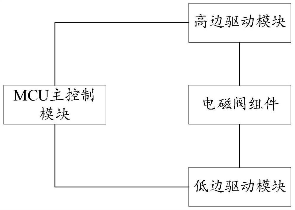
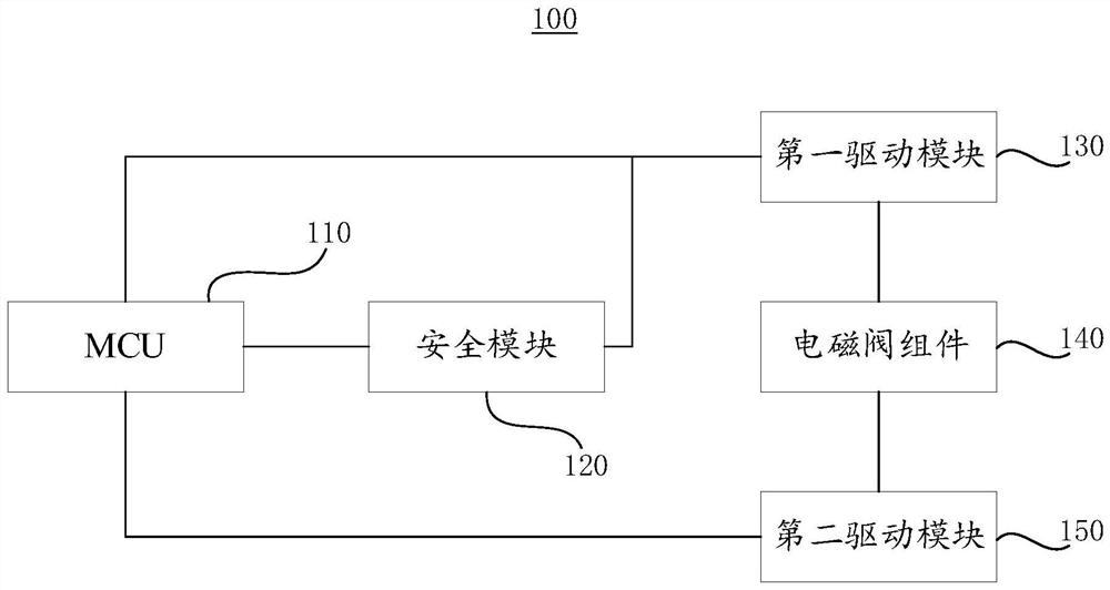
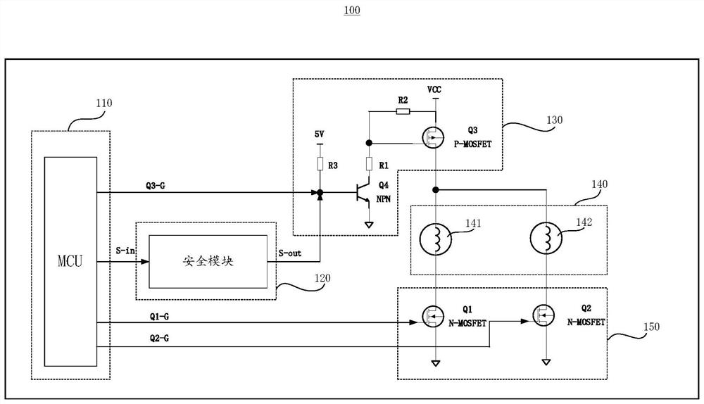
The invention provides an electromagnetic valve assembly control device and method, and relates to the technical field of electromagnetic valve assembly control. An MCU is electrically connected with a first driving module, a safety module and a second driving module, the safety module is electrically connected with the first driving module, the electromagnetic valve assembly is electrically connected with the first driving module and the second driving module, the electromagnetic valve assembly is used for being connected with a brake oil way, and the second driving module is used for being turned on or off according to a first driving signal of the MCU so as to control the opening and closing state of the electromagnetic valve assembly. The safety module is used for controlling the first driving module to be in the turned-off state when the MCU breaks down, the safety module is further used for generating a control signal according to a second driving signal of the MCU when the MCU works normally, and the first driving module is used for being turned on or turned off according to a control signal and a third driving signal of the MCU and and supplies power power to the electromagnetic valve assembly when the module is turned on. The device has the advantages that when the MCU breaks down, it can be guaranteed that the first driving module is turned off, and safety is improved.

Description

technical field [0001] The present application relates to the technical field of solenoid valve control, in particular, to a control device and method for a solenoid valve assembly. Background technique [0002] ABS (Anti-lock Braking System, anti-lock braking system) is an important part of a car or motorcycle, which is related to the safety of the driver and passengers. The control of the solenoid valve in the ABS will be directly related to the braking of the vehicle, that is, when the control of the solenoid valve fails, the vehicle may lose its braking ability, resulting in unpredictable hazards. Therefore, the control strategy and fault diagnosis of the solenoid valve in ABS are particularly important, and the solenoid valve should not be uncontrollable under any abnormal conditions. [0003] However, when the MCU (Microcontroller Unit, micro control unit) fails, the driver may not be able to brake, and there is a driving risk. [0004] To sum up, in the prior art, w...

Claims


Application Information

Patent Timeline
Patent Type & Authority Applications(China)
IPC IPC(8): F16K31/06B60T8/36B60T8/176
CPCF16K31/0675B60T8/363B60T8/176
Inventor 单东升陈赞郑飞
Owner 宁波赛福汽车制动有限公司
Learn More