Spindle assembly with air-tight structure and machine tool with same

An air sealing and main shaft technology, applied in bearing components, engine sealing, manufacturing tools, etc., can solve the problems of uneven air pressure distribution, narrow air sealing coverage, large pressure loss, etc., and achieve uniform and continuous exhaust gas. The effect of increased coverage and flow rate

Active Publication Date: 2022-05-27
GREE ELECTRIC APPLIANCES INC
View PDF5 Cites 0 Cited by
  • Summary
  • Abstract
  • Description
  • Claims
  • Application Information

AI Technical Summary

Problems solved by technology

[0003] In view of this, the present invention provides a spindle assembly with an air-tight structure and a machine tool with it to solve the problems in the prior art such as large pressure loss along the gas path, uneven air pressure distribution, narrow air-tight coverage and poor effect.

Method used


Image

  • Spindle assembly with air-tight structure and machine tool with same
  • Spindle assembly with air-tight structure and machine tool with same
  • Spindle assembly with air-tight structure and machine tool with same

Examples


Embodiment Construction

[0028] The embodiments of the present invention are described below by specific specific embodiments. Those who are familiar with the technology can easily understand other advantages and effects of the present invention from the contents disclosed in this specification. Obviously, the described embodiments are part of the present invention. , not all examples. Based on the embodiments of the present invention, all other embodiments obtained by those of ordinary skill in the art without creative efforts shall fall within the protection scope of the present invention.

[0029] The terms used in the embodiments of the present invention are only for the purpose of describing specific embodiments, and are not intended to limit the present invention. The singular forms "a," "the," and "the" as used in the embodiments of the present invention and the appended claims are intended to include the plural forms as well, unless the context clearly dictates otherwise, "a plurality" Genera...


PUM


Abstract

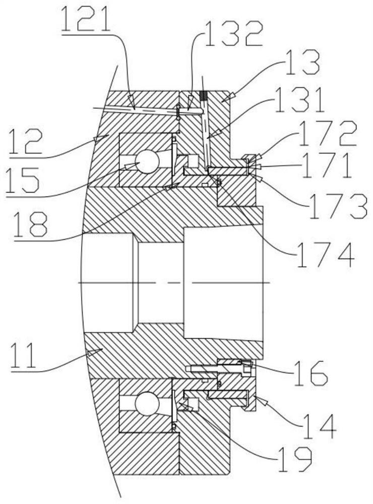
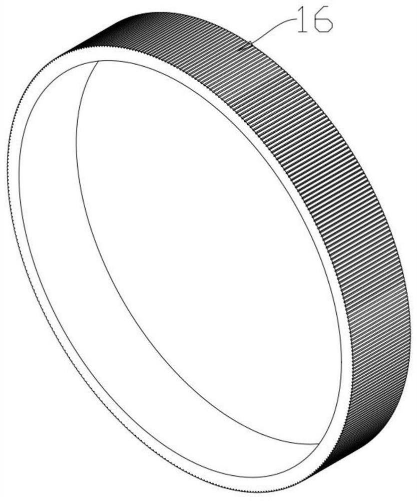
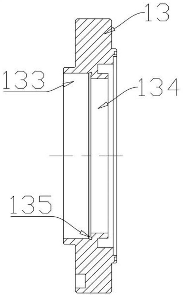
The invention provides a main shaft assembly with an air sealing structure and a machine tool with the same, including a main shaft, a bearing seat, a flange and a dynamic balance disc; the flange is formed with a flange mounting hole, and the annular boss of the dynamic balance disc is inserted It is arranged between the flange mounting hole and the main shaft, and a ring member is embedded between the annular boss and the flange mounting hole; a first channel is formed between the ring member and the flange mounting hole; between the first channel and the flange An annular cavity is formed at the communication part of the through hole; after the gas enters the first channel, the exhaust gas is uniform and continuous, the exhaust path is shortened, and the effect of air sealing is improved; the annular part is formed with a plurality of teeth, and the adjacent teeth are separated from each other. A channel is formed between the grooves, a sub-channel is formed between the channel and the mounting hole, a plurality of sub-channels constitute a first channel, a second channel is formed between the end of the flange and the dynamic balance plate, and the gas discharged from the first channel enters the second channel. channel, which removes contaminants such as cutting fluid and iron chips entering the second channel, and seals the entire circumference of the bearing.

Description

technical field [0001] The invention relates to the technical field of intelligent equipment, in particular to a spindle assembly provided with an air-sealing structure and a machine tool having the same. Background technique [0002] In the field of CNC machine tools, the electric spindle is a technology that integrates the spindle and the spindle motor. It belongs to the high-precision technology industry and is mainly used for the processing of parts. The machining process requires injection of cutting fluid, and also produces iron filings and other pollutants. When the electro-spindle is used in a high speed and complex environment, the shaft center and bearing of the electro-spindle are not allowed to enter the dirt, otherwise the life of the bearing will be reduced. In the existing main shaft air sealing structure, the gas enters the annular cavity through the radial hole and the annular groove, and the gas pressure loss along the way is large, the air pressure distrib...

Claims


Application Information

Patent Timeline
Patent Type & Authority Patents(China)
IPC IPC(8): F16J15/40F16J15/447F16C35/06B23B19/02
CPCF16J15/40F16J15/447F16C35/06B23Q1/70
Inventor 王攀耿继青邵启鹏何圳涛高威
Owner GREE ELECTRIC APPLIANCES INC
Why Eureka
Try Eureka